


[ II Restrictions ]
- 70 -
HWE09080 GB
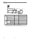
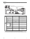
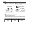
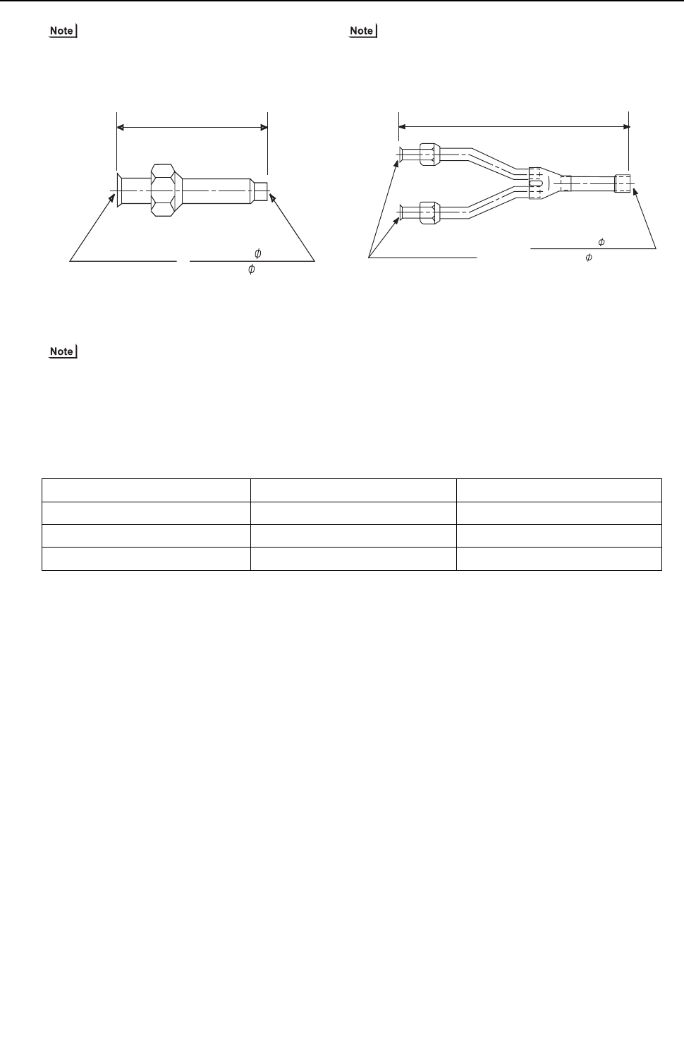
1) To connect P06 - P18 models of indoor units use
the reducer that is supplied with the BC controller.
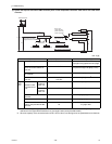
2) To connect P36 - P96 models of indoor units (or when the
total capacity of indoor units exceeds P31), use a junction
pipe kit and merge the two nozzles.
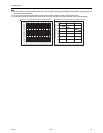
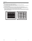
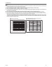
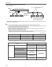
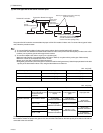
3) To connect multiple indoor units to a port (or to a junction pipe)
Maximum total capacity of connected indoor units: P54 or below (in a system with a junction pipe: P96 or below)
Maximum number of connectable indoor units: 3 units
Branch joint: Use CMY-Y102S-G2 (optional accessory).
Refrigerant pipe selection (size of the pipes in sections A and B in the figure above): Select the proper size pipes
based on the total capacity of the downstream indoor units, using the table below as a reference.
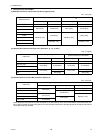
Unit : mm [inch]
Total capacity of indoor units Liquid pipe Gas pipe
P54 or below ø9.52 [3/8"] ø15.88 [5/8"]
P55 - P72 ø9.52 [3/8"] ø19.05 [3/4"]
P73 - P96 ø9.52 [3/8"] ø22.2 [7/8"]
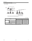
Liquid pipe side: 6.35[1/4"]ID
Gas pipe side: 12.7[1/2"]ID
Liquid pipe side:3/8F
(Flare connection)
Gas pipe side:5/8F
(Flare connection)
Note) Use the flare nut that is supplied with the BC controller.
70 [2-25/32"]
Liquid pipe side: 9.52[3/8”]ID
Gas pipe side: 19.05[3/4”]ID(*1)
234 [9-7/32"]
Supplied with a thermal insulation cover
Liquid pipe side:3/8F
(Flare connection)
Gas pipe side:5/8F
(Flare connection)