


[ II Restrictions ]
37- 37 -
HWE09080 GB
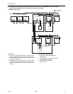
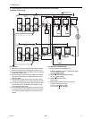
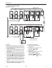
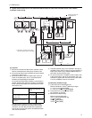
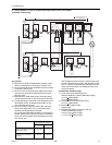
6. System with one heat source unit (automatic address setup for both indoor and heat source units) <PQRY>
(1) Sample control wiring
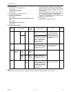
(2) Cautions
1) ME remote controller and MA remote controller cannot
both be connected to the same group of indoor units.
2) No more than 2 MA remote controllers can be connected
to a group of indoor units.
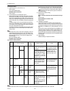
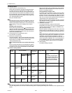
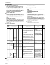
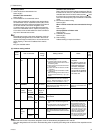
3) When the number of the connected indoor units is as
shown in the table below, one or more transmission
boosters (sold separately) are required.
To connect two transmission boosters, connect them in
parallel. (Observe the maximum number of connectable
indoor units that are listed in the specifications for each
heat source unit.)
The table above shows the number of transmission
boosters that is required by the system with three BC
controllers. For each BC controller that is subtracted
from the above-mentioned system, two additional indoor
units can be connected.
4) Automatic address setup is not available if start-stop in-
put(CN32, CN51, CN41) is used for a group operation of
indoor units. Refer to "[5] 7. Manual address setup for
both indoor and heat source units"
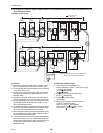
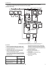
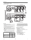
5) To connect more than 2 LOSSNAY units to indoor units
in the same system, refer to the next section "[5] 7. An
example of a system with one heat source unit to which
2 or more LOSSNAY units are connected".
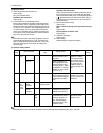
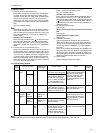
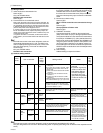
(3) Maximum allowable length
1) Indoor-heat source transmission line
Maximum distance (1.25mm
2
[AWG16] or larger)
L1 +L2+L3+L4+L5 200m[656ft]
L1 +L2+L3+L11+L12+L13 200m[656ft]
2) Transmission line for centralized control
No connection is required.
3) MA remote controller wiring
Maximum overall line length
(0.3 to 1.25mm
2
[AWG22 to 16])
m1 200m [656ft]
m2+m3 200m [656ft]
m4+m5 200m [656ft]
IC
TB5
M1
M2
M1
M2
M1
M2
M1
M2
M1
M2
M1
M2
S
TB
15
12
00
IC
TB5
S
TB
15
12
00
A1 B2
MA
A1 B2
MA
A1 B2
RC
LC
TB5
S
00
IC
TB5
S
12
TB
15
IC
TB5
S
TB
15
12
0000
IC
TB5
S
TB
15
12
00
A1 B2
MA
A1 B2
MA
A1 B2
MA
GroupGroup
GroupGroup
A1 B2
MA
m1
L11
m2
L4 L5
L12 L13
m3
m5
m4
Interlock operation with
the ventilation unit
*1. When BS is connected to the system,
automatic address setup is not available.
BC
00
OC
00
TB7
M1 M2
S
TB3
OS
00
TB7
M1 M2 M1 M2 M1 M2
S
TB3
TB02
M1 M2
S
*1
BS
TB02
00
S
M1M2
L3L1 L2
Leave the male
connector on
CN41 as it is.
SW2-1 OFF
Leave the male
connector on
CN41 as it is.
SW2-1 OFF
Number of transmission
booster (sold separately) re-
quired
1 unit 2 units
When the P72 and P96 models
are not included in the connect-
ed indoor units
27 - 50 units -
When the P72 or P96 model is
included in the connected in-
door units
21 - 39 units 40 - 50 units