


[ II Restrictions ]
- 21 -
HWE09080 GB
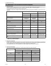
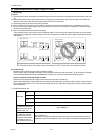
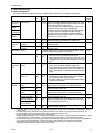
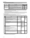
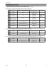
(2) Power supply switch connector connection on the heat source unit
(Factory setting: The male power supply switch connector is connected to CN41.)
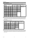
There are limitations on the total number of units that are connectable to each refrigerant system. Refer to the DATABOOK
for details.
*1 The need for a power supply unit for transmission lines depends on the system configuration.
*2 The replacement of the power jumper connector from CN41 to CN40 must be performed on only one heat source unit in
the system.
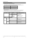
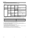
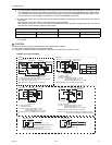
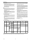
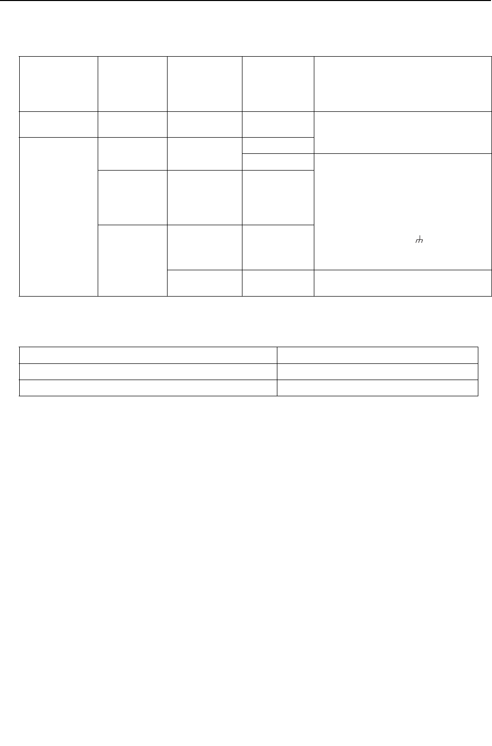
(3) Settings for the centralized control switch for the heat source unit (Factory setting: SW2-1 are set to OFF.)
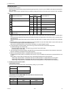
(4) Selecting the position of temperature detection for the indoor unit (Factory setting: SW1-1 set to "OFF".)
To stop the fan during heating Thermo-OFF (SW1-7 and 1-8 on the indoor units to be set to ON), use the built-in thermistor
on the remote controller or an optional thermistor.
1) To use the built-in sensor on the remote controller, set the SW1-1 to ON.
Some models of remote controllers are not equipped with a built-in temperature sensor.
Use the built-in temperature sensor on the indoor unit instead.
When using the built-in sensor on the remote controller, install the remote controller where room temperature can be detected.
(Note) Factory setting for SW1-1 on the indoor unit of the All-Fresh Models is ON.
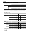
2) When an optional temperature sensor is used, set SW1-1 to OFF, and set SW3-8 to ON.
When using an optional temperature sensor, install it where room temperature can be detected.
System configura-
tion
Connection to
the system con-
troller
Power supply unit
for transmission
lines
Group operation
of units in a sys-
tem with multiple
heat source
units
Power supply switch connector connection
System with one
heat source unit
_ _ _ Leave CN41 as it is
(Factory setting)
System with multi-
ple heat source
units
Not connected _ Not grouped
Grouped Disconnect the male connector from the fe-
male power supply switch connector (CN41)
and connect it to the female power supply
switch connector (CN40) on only one of the
heat source units.
*2
*Connect the S (shielded) terminal on the
terminal block (TB7) on the heat source
unit whose CN41 was replaced with CN40
to the ground terminal ( ) on the electric
box.
With connection
to the indoor-
heat source
transmission
line
Not required Grouped/not
grouped
With connection
to the central-
ized control sys-
tem
Not required
*1
(Powered from
the heat source
unit)
Grouped/not
grouped
Required *1 Grouped/not
grouped
Leave CN41 as it is
(Factory setting)
System configuration Centralized control switch settings
*1
*1. Set SW2-1 on all heat source units in the same refrigerant circuit to the same setting.
Connection to the system controller Not connected Leave it to OFF. (Factory setting)
Connection to the system controller Connected
*2
*2. When only the LM adapter is connected, leave SW2-1 to OFF (as it is).
ON