


[ II Restrictions ]
- 22 -
HWE09080 GB
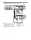
(5) Various start-stop controls (Indoor unit settings)
Each indoor unit (or group of indoor units) can be controlled individually by setting SW 1-9 and 1-10.
*1. Do not cut off power to the heat source unit. Cutting off the power supply to the heat source unit will cut off the power
supply to the crankcase heater and may cause the compressor to malfunction when the unit is put back into operation.
*2. Not applicable to units with a built-in drain pump or humidifier.
*3. Models with a built-in drain pump cannot be turned on/off by the plug individually. All the units in the same refrigerant cir-
cuits will be turned on or off by the plug.
*4. Requires that the dipswitch settings for all the units in the group be made.
*5. Set SW1-9 and SW1-10 to ON to control the external input from/output to the air conditioning units via AG-150A or G(B)-
50A using the PLC software for general equipment. With these settings made, the power start-stop function becomes dis-
abled. To use the auto recovery function after power failure while these settings are made, set SW1-5 to ON.
(6) Miscellaneous settings
Cooling-only setting for the indoor unit: Cooling only model (Factory setting: SW3-1 "OFF.")
When using indoor unit as a cooling-only unit, set SW3-1 to ON.
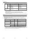
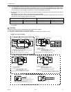
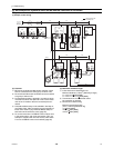
(7) Various types of control using input-output signal connector on the heat source unit (various connection options)
Function
Operation of the indoor unit when the operation is resumed after the unit
was stopped
Setting (SW1)
*4 *5
910
Power ON/OFF by the
plug
*1,*2,*3
Indoor unit will go into operation regardless of its operation status before
power off (power failure). (In approx. 5 minutes)
OFF ON
Automatic restoration
after power failure
Indoor unit will go into operation if it was in operation when the power was
turned off (or cut off due to power failure). (In approx. 5 minutes)
ON OFF
Indoor unit will remain stopped regardless of its operation status before
power off (power failure).
OFF ON
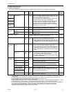
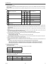
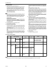
Type Usage Function
Terminal to be
used
*1
*1. For detailed drawing, refer to "Example of wiring connection".
Option
Input Prohibiting cooling/heating operation (thermo OFF) by an ex-
ternal input to the heat source unit.
* Usable for demand control of each refrigerant system
DEMAND (level) CN3D
*2
*2. For details, refer to the next section "Demand control".
Adapter
for exter-
nal input
(PAC-
SC36NA-
E)
Performs a low level noise operation of the heat source unit by
an external input to the heat source unit.
* It can be used as the silent operation device for each refriger-
ant system.
Low-noise mode
(level)
*3 *4
Cooling/heating operation can be changed by an external input
to the heat source unit (OC).
Auto-changeover CN3N
Receives interlock operation signal input from the water circuit
pump (field-supplied)
Pump interlock
operation signal
input
TB-8 (between
poles 3 and 4)
*Minimum guar-
anteed current at
no-voltage input
contact: 5 mA or
below
_
Out-
put
Outputs signals to perform interlocked operation of heat source
unit and water circuit pump
Signal output patterns
*When DIP SW2-7 is set to off (factory setting)
Signals are output while the compressor is in operation.
*When DIP SW2-7 is set to ON
Signals are output from the controller while receiving cool-
ing or heating signal.
Signals are output while the compressor is stopped during
Thermo-OFF.
Pump interlock
operation signal
TB-8 (between
poles 1 and 2)
*Contact rating:
200VAC 1A or
below
_
How to extract signals from the heat source unit
*It can be used as an operation status display device.
*It can be used for an interlock operation with external devic-
es.
Operation status
of the compressor
CN51 Adapter
for exter-
nal output
(PAC-
SC37SA-
E)
Error status