


[ VI Refrigerant Circuit ]
- 131 -
HWE09080 GB
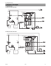
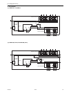
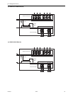
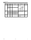
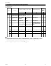
(2) GA type
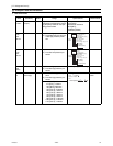
Part name
Symbols
(functions)
Part
code
Usage Specifications Check method
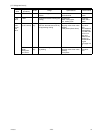
Pressure
sensor
PS1
(High pres-
sure side)
1) Detects high pressure
2) LEV control
PS3
(Intermedi-
ate pres-
sure)
1) Detects intermediate
pressure
2) LEV control
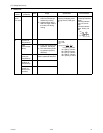
Thermistor TH11
(Liquid inlet
tempera-
ture)
LEV control
(Liquid level control)
0°C[32°F] : 15kohm
10°C[50°F] :9.7kohm
20°C[68°F] :6.4kohm
25°C[77°F] :5.3kohm
30°C[86°F] :4.3kohm
40°C[104°F] :3.1kohm
TH12
(Bypass
outlet tem-
perature)
LEV control (Superheat)
TH15
(Bypass in-
let tempera-
ture)
LEV control (Superheat)
TH16
(Liquid re-
frigerant
tempera-
ture)
LEV control (Subcool)
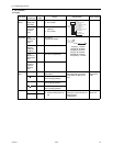
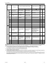
Solenoid
valve
SVM1 Opens during cooling and de-
frost modes
AC208-230V
Open while being powered/
closed while not being pow-
ered
Continuity
check with a
tester
SVM2 Pressure differential control
SV A Provides refrigerant to indoor
unit in cooling operation
SV B Provides refrigerant to indoor
unit in heating operation
SV C Provides refrigerant to indoor
unit in cooling operation
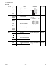
LEV LEV1
LEV2
1) Liquid level control
2) Pressure differential con-
trol
DC12V
Opening of a valve driven by a
stepping motor
0-2000 pulses
Same as
indoor LEV
LEV3 Subcool control
Pressure
0~4.15 MPa [601psi]
Vout 0.5~3.5V
0.071V/0.098 MPa [14psi]
Pressure [MPa]
=1.38 x Vout [V]-0.69
Pressure [psi]
=(1.38 x Vout [V] - 0.69) x 145
GND (Black)
Vout (White)
Vcc (DC5V) (Red)
Con-
nector
PS1
1
123
2
3
R = 15k
0
R = 3460
R = 15
0/80
t
3460
273 t
1
273
1
exp