


[ IX Troubleshooting ]
- 349 -
HWE09080 GB
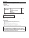
No. Parts to be replaced
1 Water-cooled heat
exchanger assembly
2 Check valve (CV8)
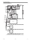
1. Water heat exchanger assembly and check valve (CV8) replacement instructions
* The following describes the procedures for replacing the water heat exchanger assembly and check valve (CV8).
1. Applicable models
• PQHY-P72, 96, 120YHMU-A
• PQRY-P72, 96, 120YHMU-A
2. Parts to be serviced, Set-contents
Required materials
Water-cooled heat exchanger service parts kit
[Kit contents]
Instructions sheet
Water-cooled heat exchanger assembly
Check valve service parts kit
[Kit contents]
Instructions sheet
Check valve assmbly
Connecting pipe
Qty.
1 kit
1
1
1 kit
1
1
1
3. Procedures
* Precautions for starting replacement
• Check that the main power supply is OFF.
• Check that no refrigerant is in the heat source unit.
Remove each part according to the 1)-3) procedures on the next page before replacing service parts.
Mount the removed parts back in place in a reversed procedures of 1)-3) on the next page after replacing service
parts.
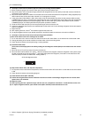
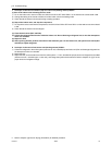
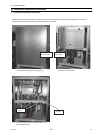
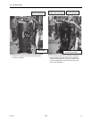
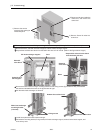
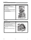
(1) Water-cooled heat exchanger assembly replacement procedures
Removal procedures
Remove the duct, solenoid valve block support, and INV heat exchanger support.
Hand the solenoid valve block support with wire from the beam so that it will not fall.
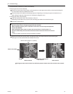
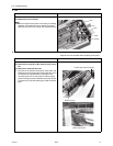
Remove the fastening plate and the screws holding the water-cooled heat exchanger, and
remove the braze
Pull the water-cooled heat exchanger forward toward the front of the unit.
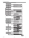
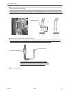
Installation procedures
Install the water-cooled heat exchanger included in the replacement parts kit
Reinstall the fastening plate, fixing screws, INV heat exchanger support, solenoid valve block
support, and the duct.
* Precautions for replacing water-cooled heat exchanger assembly
• Be sure to perform no-oxidation brazing when brazing.
• After brazing, check the condition around the brazing. After confirming no leakage, evacuate the air
inside. (*1)
• Perform brazing with care of the flame direction so that it does not burn cables and plates etc. in the unit.
*1: Refer to Chapter I [8] Vacuum Drying (Evacuation) for detailed procedure.
1
2
3
4
6
7