


- 34 -
[ II Restrictions ]
GBHWE09080
(4) Wiring method
1) Indoor-heat source transmission line
Same as [5] 1.
Only use shielded cables.
Shielded cable connection
Same as [5] 1.
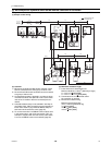
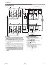
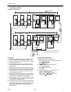
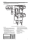
2) Transmission line for centralized control
Daisy-chain terminals A and B on the system controller,
terminals M1 and M2 on the terminal block for transmis-
sion line for centralized control (TB7) on the heat source
units (OC) in different refrigerant circuits and on the heat
source units (OC, OS1, and OS2) in the same refrigerant
circuit.
If a power supply unit is not connected to the transmis-
sion line for centralized control, replace the power jump-
er connector on the control board from CN41 to CN40 on
only one of the heat source units.
If a system controller is connected, set the central control
switch (SW2-1) on the control board of all heat source
units to "ON."
The heat source units in the same refrigerant circuit are
automatically designated as OC, OS1, and OS2 in the
order of capacity from large to small (if two or more units
have the same capacity, in the order of address from
small to large).
Only use shielded cables.
Shielded cable connection
Daisy-chain the S terminal on the terminal block (TB7) on
the heat source units (OC, OS1, OS2) with the shield
wire of the shielded cable. Short-circuit the earth terminal
( ) and the S terminal on the terminal block (TB7) on
the heat source unit whose power jumper connector is
mated with CN40.
3) MA remote controller wiring
Same as [5] 1.
When 2 remote controllers are connected to the sys-
tem
Same as [5] 1.
Group operation of indoor units
Same as [5] 1.
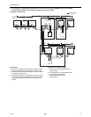
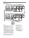
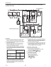
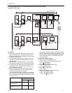
4) LOSSNAY connection
Connect terminals M1 and M2 on the terminal block
(TB5) on the indoor unit (IC) to the appropriate terminals
on the terminal block for indoor-heat source transmission
line (TB5) on LOSSNAY (LC). (Non-polarized 2-core ca-
ble)
Indoor units must be interlocked with the LOSSNAY unit
using the system controller. (Refer to the operation man-
ual for the system controller for the setting method.) In-
terlock setting from the remote controller is required if the
ON/OFF remote controller alone or the LM adapter alone
is connected.
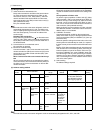
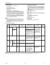
5) Switch setting
Address setting is required as follows.
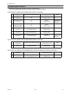
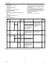
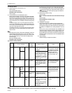
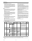
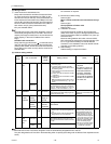
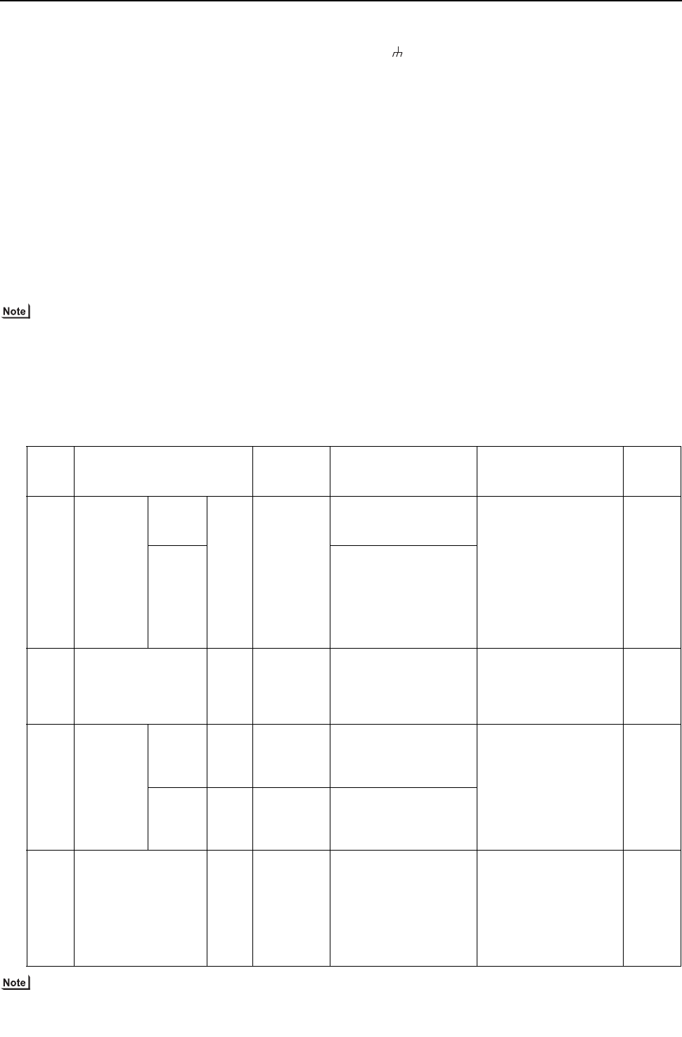
(5) Address setting method
The heat source units in the same refrigerant circuit are automatically designated as OC, OS1, and OS2.
Proce-
dures
Unit or controller
Address
setting
range
Setting method Notes
Factory
setting
1 Indoor unit Main unit IC 01 to 50 Assign the smallest ad-
dress to the main unit in
the group.
To perform a group oper-
ation of indoor units that
have different functions,
designate the indoor unit
in the group with the
greatest number of func-
tions as the main unit.
00
Sub unit Assign sequential num-
bers starting with the ad-
dress of the main unit in
the same group +1. (Main
unit address +1, main unit
address +2, main unit ad-
dress +3, etc.)
2 LOSSNAY LC 01 to 50 Assign an arbitrary but
unique address to each of
these units after assign-
ing an address to all in-
door units.
None of these addresses
may overlap any of the in-
door unit addresses.
00
3MA
remote con-
troller
Main
remote
control-
ler
MA No
settings re-
quired.
- Enter the same indoor
unit group settings on the
system controller as the
ones that were entered
on the MA remote con-
troller.
Main
Sub
remote
control-
ler
MA Sub
remote con-
troller
Settings to be made ac-
cording to the remote
controller function selec-
tion
4 Heat source unit OC
OS1
OS2
51 to 100 Assign sequential ad-
dress to the heat source
units in the same refriger-
ant circuit.
The heat source units are
automatically designated
as OC, OS1, and
OS2.(Note)
To set the address to
100, set the rotary switch-
es to 50.
00