


[ IX Troubleshooting ]
- 320 -
HWE09080 GB
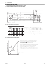
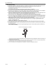
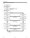
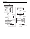
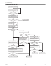
1) For the connectors on the board, TH11 and TH12 are connected to CN10, and TH15 and TH16 are connected to CN11. Dis-
connect the connector in trouble, and check the sensor of each number.
2)
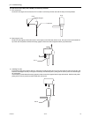
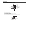
Pull out the sensor connector from the I/O board, Do not pull the sensor by holding the lead wire.
Measure the resistance with such as a tester.
Compare the measured value with that of shown in the figure below. When the result is 10%, it is normal.
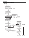
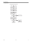
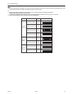
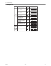
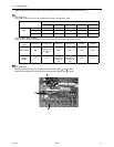
3) Check the self-diagnosis switch (Heat source control board SW1).
12345678910
ON
12345678910
ON
12345678910
ON
12345678910
ON
12345678910
ON
12345678910
ON
12345678910
ON
12345678910
ON
TH12
TH15
TH12
TH15
Liquid inlet temperature
Bypass outlet temperature
Bypass outlet temperature
Bypass outlet temperature
TH11
TH12
Bypass inlet temperature
Bypass inlet temperature
Bypass inlet temperature
Bypass inlet temperature
TH15
TH16
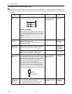
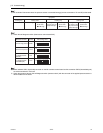
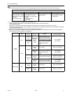
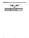
Measurement data SW1 setting value Symbol
G, GA
(Standard / main)
GB, HB
(Sub 1)
GB, HB
(Sub 2)