


[ II Restrictions ]
- 23 -
HWE09080 GB
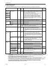
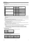
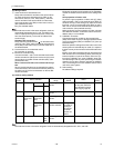
*4. By setting Dip SW5-5, the Low-noise mode can be switched between the Capacity priority mode and the Low-noise pri-
ority mode.
When SW5-5 is set to ON: The low-noise mode always remains effective.
When SW5-5 is set to OFF: The low noise mode is cancelled when certain operation pressure criteria are met, and the
unit goes into normal operation (capacity priority mode).
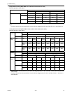
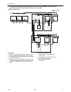
*5. When multiple heat source units exist in one refrigerant circuit system, settings on every heat source unit (signal input)
are required.
CAUTION
1) Wiring should be covered by insulation tube with supplementary insulation.
2) Use relays or switches with IEC or equivalent standard.
3) The electric strength between accessible parts and control circuit should have 2750V or more.
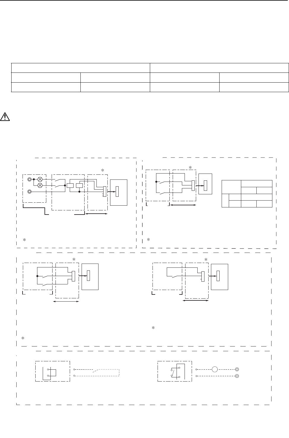
Example of wiring connection
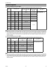
*3. Low-noise mode is valid when Dip SW4-4 on the heat source unit is set to OFF. When DIP SW4-4 is set to ON, 4 levels
of on-DEMAND are possible, using different configurations of low-noise mode input and DEMAND input settings.When
2 or more heat source units exist in one refrigerant circuit system, 8 levels of on-DEMAND are possible. When 3 heat
source units exist in one refrigerant circuitsystem, 12 levels of on-DEMAND are possible.
Low-noise mod is effective. Capacity priority mode becomes effective.
Cooling Heating Cooling Heating
63HS1<32kg/cm
2
63LS>4.6kg/cm
2
63HS1>35kg/cm
2
63LS<3.9kg/cm
2
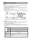
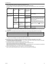
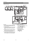
(1) CN51
CN51
X
Y
L
1
L
2
ecruos rewop pmaL
Distant control
board
Relay circuit Adapter
1
Heat source unit
control board
Preparations
in the field
Maximum cable
length is 10m
5
4
3
X
Y
L1 : Heat source unit error display lamp
L2 : Compressor operation lamp (compressor running state)
X, Y : Relay (coil =<0.9W : DC12V)
1. Optional part : PAC-SC37SA-E or field supply.
(2) CN3N
2. Optional part : PAC-SC36NA-E or field supply.
Preparations
in the field
OFF
Cooling
ON
Heating
Normal
Y
OFF
ON
X
Contact rating voltage >= DC15V
Contact rating current >= 0.1A
Minimum applicable load =< 1mA at DC
X : Cooling / Heating
Y : Validity / Invalidity of X
X,Y : Relay
CN3N
X
Y
Relay circuit
Adapter
2
Heat source unit
control board
Maximum cable
length is 10m
1
2
3
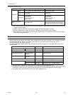
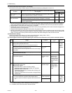
(3) CN3D
2. Optional part : PAC-SC36NA-E or field supply.
X : Low-noise mode
X : Low-noise mode
Y : Compressor ON/OFF
X,Y : Relay
Contact rating voltage >= DC15V
Contact rating current >= 0.1A
Minimum appicable load =< 1mA at DC
Y
X
CN3D
TB8 TB8
3
X
63PW
4
1
2
Preparations
in the field
Maximum cable
length is 10m
Adapter
2
Heat source unit
control board
3
2
1
Relay circuit
Heat source unit
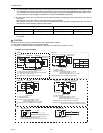
Pump interlock circuit (if one is connected)
63PW: Pressure switch (Contact: Minimum applied load 5 mA)
X: Relay (Contact rating: 200VAC 1A)
52P: Pump contactor
When connecting the pump interlock circuit wires to terminals
3 and 4 of TB8, remove the short-circuit wire.
Heat source unit
Short-
circuit
wire
2. Optional part : PAC-SC36NA-E or field supply.
X
CN3D
Preparations
in the field
Maximum cable
length is 10m
Adapter
2
Heat source unit
control board
2
3
1
X : Relay
fan frequency and maximum compressor frequency.
Contact rating voltage >= DC15V
Contact rating current >= 0.1A
Minimum applicable load =< 1mA at DC
Low-noise mode : The noise level is reduced by controlling the maximum
Relay circuit
(4)TB8
52P