


[ IX Troubleshooting ]
- 345 -
HWE09080 GB
5. Leak spot: In the case of extension pipe for indoor unit (Cooling season)<PQRY>
1) Mount a pressure gauge on the service check joint (CJ2) on the low-pressure side.
2) Stop all the indoor units, and close the high-pressure side refrigerant service valve (BV2) on the heat source unit while the
compressor is being stopped.
3) Stop all the indoor units; turn on SW2-4 on the heat source unit control board while the compressor is being stopped.(Pump
down mode will start, and all the indoor units will run in cooling test run mode.)
4) In the pump down mode (SW2-4 is ON), all the indoor units will automatically stop when the low pressure (63LS) reaches
0.383MPa [55psi] or less or 15 minutes have passed after the pump mode started. Stop all the indoor units and compressors
when the pressure indicated by the pressure gauge, which is on the check joint (CJ2) for low-pressure service, reaches
0.383MPa [55psi] or 20 minutes pass after the pump down operation is started.
5) Close the service ball valve (BV1) on the low-pressure pipe on the heat source unit.
6) Collect the refrigerant that remains in the extended pipe for the indoor unit. Do not discharge refrigerant into the atmosphere
when it is collected.
7) Repair the leak.
8) After repairing the leak, vacuum
*1
the extension pipe and the indoor unit.
9) To adjust refrigerant amount, open the ball valves (BV1 and BV2) inside the heat source unit and turn off SW2-4.
6. Leak spot: In the case of heat source unit (Cooling season)<PQRY>
(1) Run all the indoor units in the cooling test run mode.
1) To run the indoor unit in test run mode, turn SW3-2 from ON to OFF when SW3-1 on the heat source control board is ON.
2) Change the setting of the remote controller for all the indoor units to the cooling mode.
3) Check that all the indoor units are performing a cooling operation.
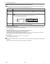
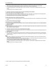
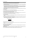
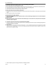
(2) Check the SC16 value.
(This valve can be displayed on the LED by setting the self-diagnosis switch (SW1) on the heat source unit control
board.)
1) When SC16 is 10°C [18°F] or above: Go to the next item (3).
2) When the SC16 value is below 10°C [18°F] : After the compressor has stopped, extract the refrigerant in the system, repair
the leak, evacuate the air from the system
*1
, and charge the system with refrigerant. (If the leak is in the heat source unit,
follow the same procedure as listed under "heating season.")
(3) Stop all the indoor units, and stop the compressor.
1) To stop all the indoor units and the compressors, turn SW3-2 from ON to OFF when SW3-1 on the heat source control board
is ON.
2) Check that all the indoor units are being stopped.
(4) Close the ball valves (BV1 and BV2).
(5) Collect the refrigerant that remains inside the heat source unit.Do not discharge refrigerant into air into the atmo-
sphere when it is collected.
(6) Repair the leak.
(7) After repairing the leak, replace the dryer with the new one, and perform evacuation
*1
inside the heat source unit.
(8) To adjust refrigerant amount, open the ball valves (BV1 and BV2) inside the heat source unit.
*1. Refer to Chapter I [8] Vacuum Drying (Evacuation) for detailed procedure.
SC16 self-diagnosis switch
1 2 3 4
5
6
7
8 10 9
ON