


- 52 -
[ II Restrictions ]
GBHWE09080
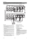
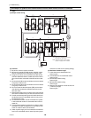
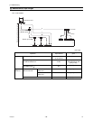
(4) Wiring method
1) Indoor-heat source transmission line
Same as [5] 8.
Shielded cable connection
Same as [5] 6.
2) Transmission line for centralized control
Same as [5] 9.
Shielded cable connection
Same as [5] 9.
3) ME remote controller wiring
ME remote controller is connectable anywhere on the in-
door-heat source transmission line.
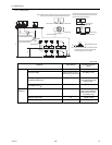
When 2 remote controllers are connected to the sys-
tem
Refer to the section on Switch Setting.
Performing a group operation (including the group
operation of units in different refrigerant circuits).
Refer to the section on Switch Setting.
4) LOSSNAY connection
Same as [5] 9.
5) Switch setting
Address setting is required as follows.
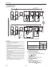
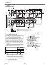
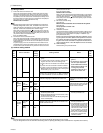
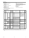
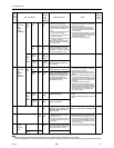
(5) Address setting method
The heat source units in the same refrigerant circuit are automatically designated as OC and OS.
They are designated as OC and OS in the descending order of capacity (ascending order of address if the capacities are the
same).
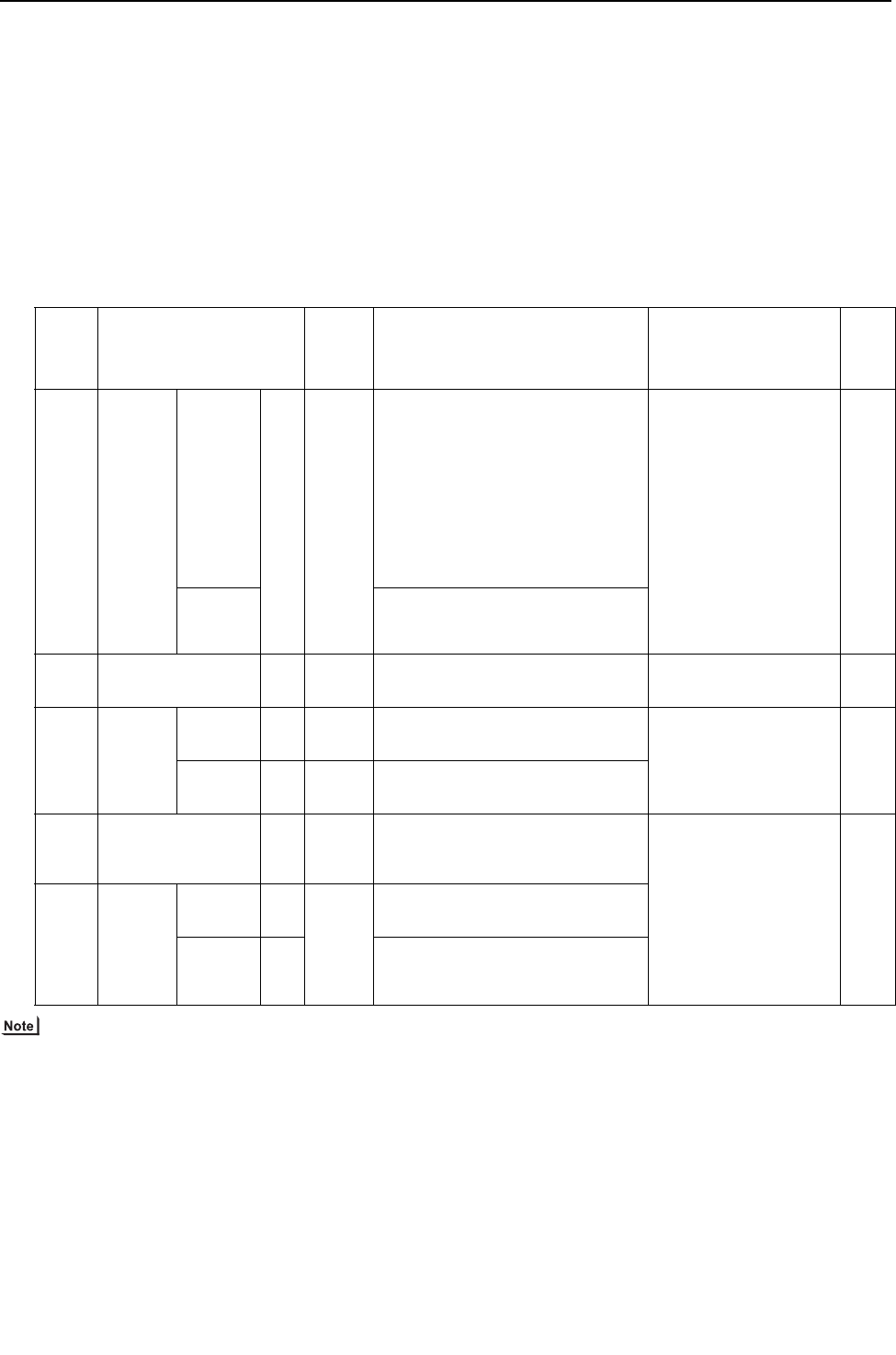
Proce-
dures
Unit or controller
Ad-
dress
setting
range
Setting method Notes
Fac-
tory
set-
ting
1 Indoor
unit
Main unit IC 01 to
50
Assign the smallest address to the main unit
in the group.
In a system with a sub BC controller, make
the settings for the indoor units in the fol-
lowing order.
(i) Indoor unit to be connected to the main BC
controller
(ii) Indoor unit to be connected to sub BC
controller 1
(iii) Indoor unit to be connected to sub BC
controller 2
Make the settings for the indoor units in the
way that the formula "(i) < (ii) < (iii)" is true.
Port number setting is
required
To perform a group op-
eration of indoor units
that have different func-
tions, set the indoor unit
in the group with the
greatest number of
functions as the main
unit.
00
Sub unit
Assign sequential numbers starting with the
address of the main unit in the same group
+1. (Main unit address +1, main unit address
+2, main unit address +3, etc.)
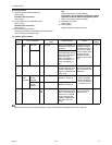
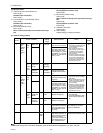
2 LOSSNAY LC 01 to
50
Assign an arbitrary but unique address to
each of these units after assigning an address
to all indoor units.
None of these addresses may
overlap any of the indoor unit
addresses.
00
3ME
remote
controller
Main
remote con-
troller
RC 101 to
150
Add 100 to the main unit address in
the group
It is not necessary to set the
100s digit.
To set the address to 200,
set the rotary switches to 00.
101
Sub
remote con-
troller
RC 151 to
200
Add 150 to the main unit address in
the group
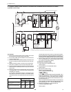
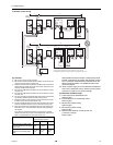
4 Heat source unit OC
OS
51 to 100 Assign sequential address to the heat
source units in the same refrigerant circuit.
The heat source units are automatically
designated as OC and OS.(Note)
To set the address to 100,
set the rotary switches to 50.
If the addresses that is as-
signed to the main BC con-
troller overlaps any of the
addresses that are assigned
to the heat source units or to
the sub BC controller, use a
different, unused address
within the setting range.
The use of a sub BC control-
ler requires the connection
of a main BC controller.
00
5 Auxiliary
heat
source
unit
BCcon-
troller (Sub)
BS
51 to 100 Assign an address that equals the sum of the
smallest address of the indoor units that are
connected to the sub BC controller and 50.
BC control-
ler (Main)
BC OC (or OS if it exists) +1