


[ IX Troubleshooting ]
- 339 -
HWE09080 GB
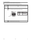
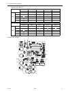
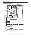
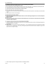
-7- Control Circuit (THMU-A)
(1) Control power source function block
Heat source unit
Power source system (AC 208 / 230 V)
Control system (DC 5 ~ 30 V)
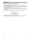
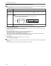
* MA remote controllers and M-NET remote controllers cannot be used together.
(Both the M-NET and MA remote controller can be connected to a system with a system controller.)
A, B
A, B
M-NET
transmission line
(Non-polar 2 wire)
AC 208 / 230 V
AC Power source
To next unit
(Indoor unit)
MA remote controller wiring
(Non-polar 2 wire)
DC 17 ~ 30 V
DC 9 ~ 12 V
M-NET remote
controller
MA remote
controller
Indoor unit
TB2
TB15
Terminal block for
power source
TB5
Terminal block
for MA remote
controller
Terminal block
for transmission
line connection
DC 17 ~ 30 V
AC 208 / 230 V
Terminal block for
power source
TB1
Noise filter
Noise filter
Fuse
Fuse
Fuse
LEV
Surge protection
INV board
Control board
63H1
72C
DCL
DC / DC converter
Detection circuit for
the power supply to
the transmission line
M-NET board
DC / DC
converter
Microcomputer
Microcomputer
5 V Power supply
18 V Power supply
12V Power supply
30 V Power supply
Relay drive circuit
Relay
5 V Power supply
17V Power supply
Smoothing capacitor
Inverter
Inverter drive
circuit
Inverter reset
circuit
Rectifier
Compressor
Smoothing capacitor
Relay, LEV
Drive circuit
72C
Solenoid valve
4-way valve
CH11
CN40
Terminal block for
transmission line
for centralized control
(DC 24 ~ 30 V)
TB7
Indoor/heat source
transmission block
(DC 24 ~ 30 V)
TB3
[THMU-A]