


- 28 -
[ II Restrictions ]
GBHWE09080
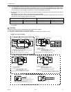
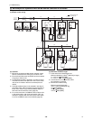
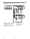
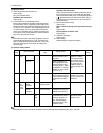
(4) Wiring method
1) Indoor-heat source transmission line
Daisy-chain terminals M1 and M2 on the terminal block
for indoor-heat source transmission line (TB3) on the
heat source units (OC, OS1, OS2) (Note 1), and termi-
nals M1 and M2 on the terminal block for indoor-heat
source transmission line (TB5) on each indoor unit (IC).
(Non-polarized two-wire)
Only use shielded cables.
The heat source units in the same refrigerant circuit are
automatically designated as OC, OS1, and OS2 in the
order of capacity from large to small (if two or more units
have the same capacity, in the order of address from
small to large).
Shielded cable connection
Daisy-chain the ground terminal ( ) on the heat source
units (OC, OS1, OS2), and the S terminal on the terminal
block (TB5) on the indoor unit (IC) with the shield wire of
the shielded cable.
2) Transmission line for centralized control
No connection is required.
3) MA remote controller wiring
Connect terminals 1 and 2 on the terminal block for MA
remote controller line (TB15) on the indoor unit (IC) to the
terminal block on the MA remote controller (MA). (Non-
polarized two-wire)
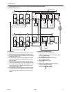
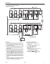
When 2 remote controllers are connected to the sys-
tem
When 2 remote controllers are connected to the system,
connect terminals 1 and 2 of the terminal block (TB15) on
the indoor unit (IC) to the terminal block on the two MA
remote controllers.
Set one of the MA remote controllers to sub. (Refer to
MA remote controller function selection or the installation
manual for the MA remote controller for the setting meth-
od.)
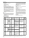
Group operation of indoor units
To perform a group operation of indoor units (IC), daisy-
chain terminals 1 and 2 on the terminal block (TB15) on
all indoor units (IC) in the same group, and then connect
terminals 1 and 2 on the terminal block (TB15) on the in-
door unit on one end to the terminal block on the MA re-
mote controller. (Non-polarized two-wire)
When performing a group operation of indoor units that
have different functions, "Automatic indoor-heat source
address setup" is not available.
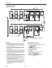
4) LOSSNAY connection
Connect terminals M1 and M2 on the terminal block
(TB5) on the indoor unit (IC) to the appropriate terminals
on the terminal block (TB5) on LOSSNAY (LC). (Non-po-
larized two-wire)
Interlock operation setting with all the indoor units in the
same system will automatically be made. (It is required
that the Lossnay unit be turned on before the heat source
unit.)
Refer to "[5] 2. Manual address setup for both indoor and
heat source units" in the following cases: performing an
interlock operation of part of the indoor units in the sys-
tem with a LOSSNAY unit, using LOSSNAY alone with-
out interlocking it with any units, performing an interlock
operation of more than 16 indoor units with a LOSSNAY
unit, or connecting two or more LOSSNAY units to indoor
units in the same system.
5) Switch setting
No address settings required.
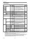
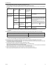
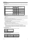
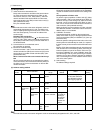
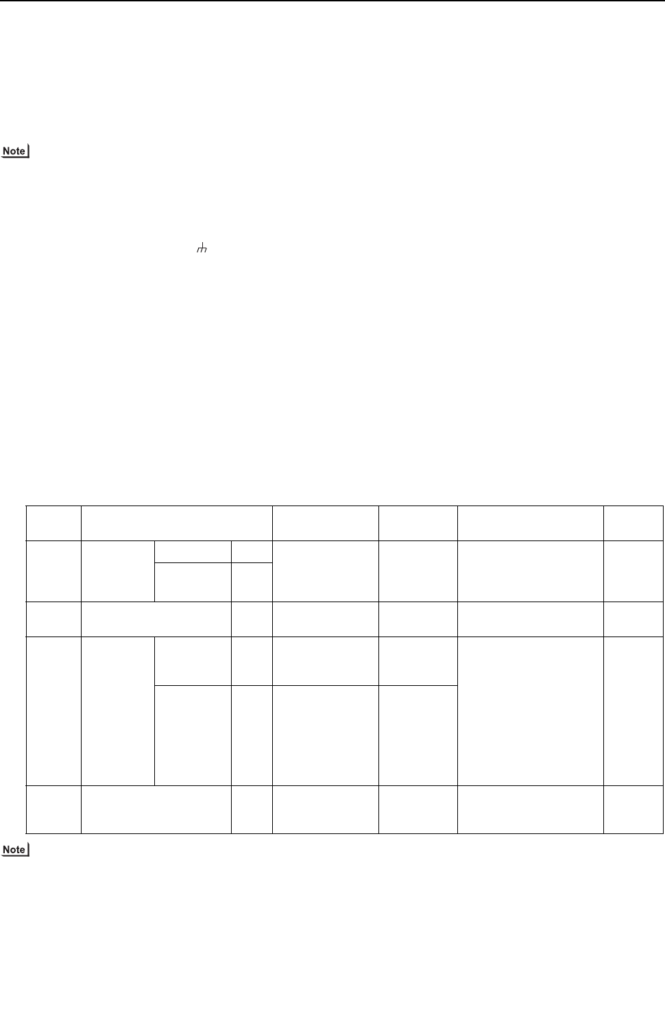
(5) Address setting method
The heat source units in the same refrigerant circuit are automatically designated as OC, OS1, and OS2.
Proce-
dures
Unit or controller
Address setting
range
Setting
method
Notes
Factory
setting
1 Indoor unit Main unit IC No settings re-
quired.
- To perform a group opera-
tion of indoor units that
have different functions,
refer to [5] 2.(page 29)
00
Sub unit IC
2 LOSSNAY LC No settings re-
quired.
-00
3MA
remote con-
troller
Main
remote con-
troller
MA No settings re-
quired.
-Main
Sub
remote con-
troller
MA Sub
remote controller
Settings to
be made ac-
cording to
the remote
controller
function se-
lection
4 Heat source unit (Note) OC
OS1
OS2
No settings re-
quired.
-00