


[ IX Troubleshooting ]
- 311 -
HWE09080 GB
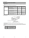
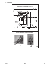
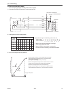
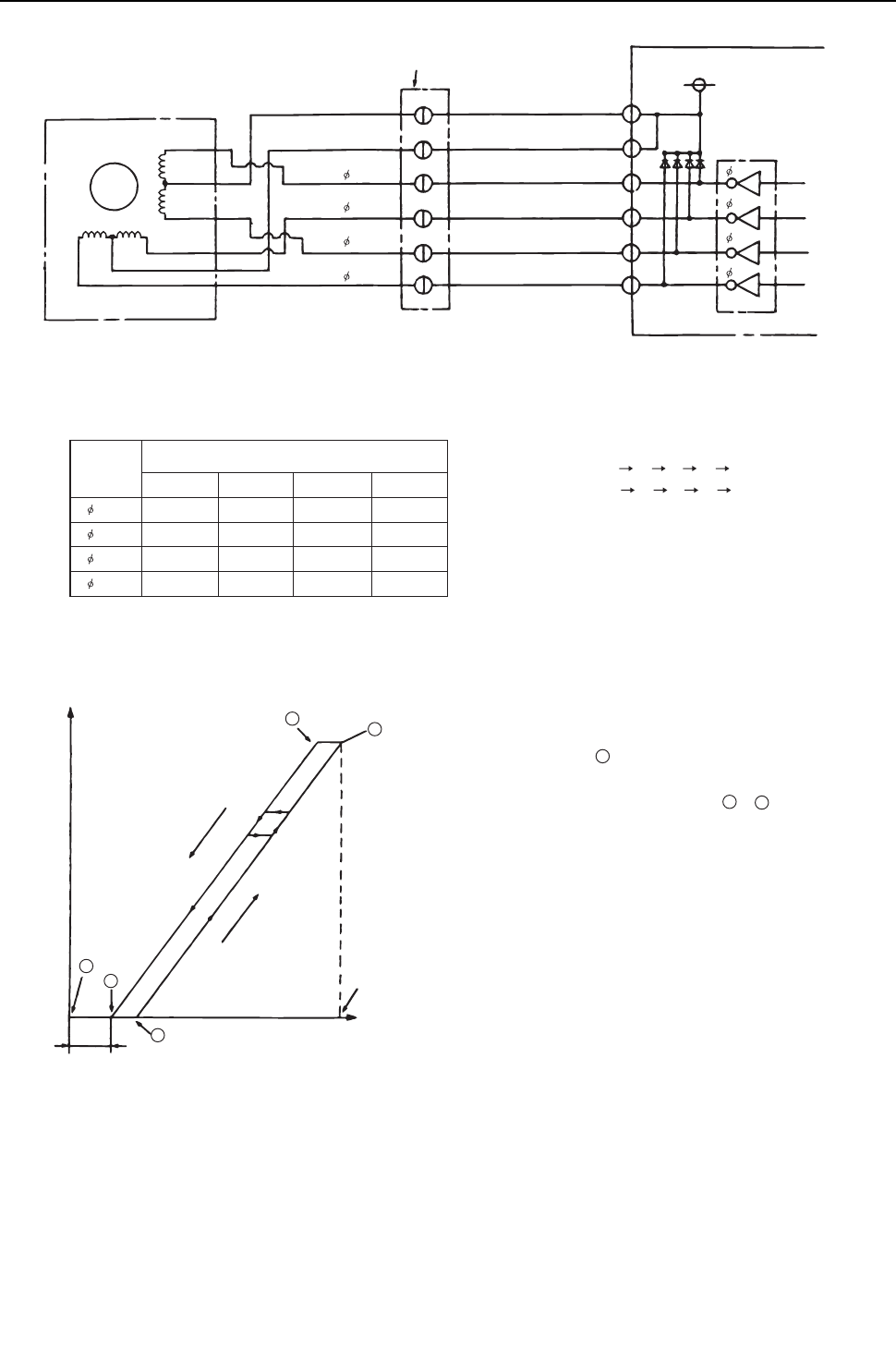
2) Pulse signal output and valve operation
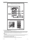
3) LEV valve closing and opening operation
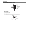
Note. The connector numbers on the intermediate connector and the connector on the control board differ. Check the color of the lead wire
to judge the number.
Heat source control board
Drive circuit
LEV
M
5
5
2
2
1
1
3
3
4
4
6
6
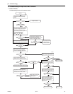
DC12V
Red
Intermediate connector
Brown
Blue
Orange
Yellow
White
Red
Orange
White
Brown
Blue
Yellow
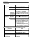
6
5
4
4
3
2
1
3
2
1
4
3
2
1
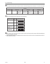
Output state
Output
(phase)
number
1234
1 ON OFF OFF ON
2 ON ON OFF OFF
3 OFF ON ON OFF
4 OFF OFF ON ON
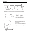
Output pulses change in the following orders when the
Valve is closed; 1 2 3 4 1
Valve is open;
4 3 2 1 4
*1. When the LEV opening angle does not change,
all the output phases will be off.
*2. When the output is open phase or remains ON,
the motor cannot run smoothly, and rattles and vibrates.
*When the power is turned on, the valve closing signal of 2200 pulses
will be output from the indoor board to LEV to fix the valve position.
It must be fixed at point A.
When the valve operates smoothly, no sound from LEV or no vibration
occurs, however, when the pulses change from E to A in the chart or
the valve is locked, a big sound occurs.
*Whether a sound is generated or not can be determined by
holding a screwdriver against it, then placing your ear against the handle.
Valve opening (refrigerant flow rate)
Valve closed
Valve open
E
B
80 - 100 pulses
Pulses
Fully open: 1400 pulses
A
C
D