


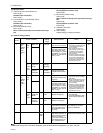
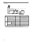
[ II Restrictions ]
55- 55 -
HWE09080 GB
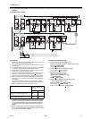
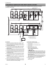
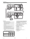
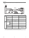
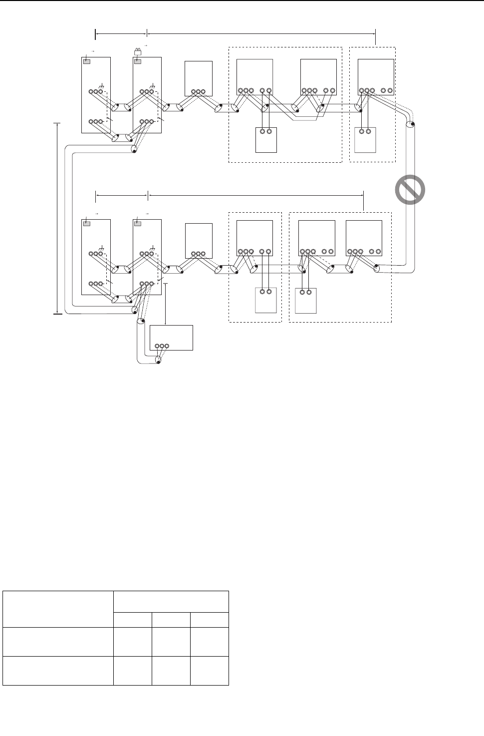
2. PQRY
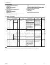
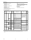
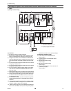
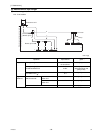
(1) Sample control wiring
(2) Cautions
1) Be sure to connect a system controller.
2) ME remote controller and MA remote controller cannot both be con-
nected to the same group of indoor units.
3) Assign to the indoor units connected to the MA remote controller ad-
dresses that are smaller than those of the indoor units that are con-
nected to the ME remote controller.
4) No more than 2 ME remote controllers can be connected to a group
of indoor units.
5) No more than 2 MA remote controllers can be connected to a group
of indoor units.
6) Do not connect the terminal blocks (TB5) on the indoor units that are
connected to different heat source units with each other.
7) Replace the power jumper connector of the control board from CN41
to CN40 on only one of the heat source units.
8) Provide an electrical path to ground for the S terminal on the terminal
block for centralized control on only one of the heat source units.
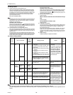
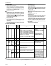
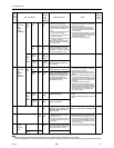
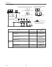
9) When the number of the connected indoor units is as shown in the
table below, one or more transmission boosters (sold separately)
are required.
To connect two transmission boosters, connect them in parallel.
(Observe the maximum number of connectable indoor units that are
listed in the specifications for each heat source unit.)
The left table shows the number of transmission boost-
ers that is required by the system with three BC control-
lers. For each BC controller that is subtracted from the
above-mentioned system, two additional indoor units
can be connected.
10) When a power supply unit is connected to the transmis-
sion line for centralized control, leave the power jumper
connector on CN41 as it is (factory setting).
(3) Maximum allowable length
1) Indoor-heat source transmission line
Same as [5] 8.
2) Transmission line for centralized control
Same as [5] 9.
3) MA remote controller wiring
Same as [5] 6.
4) ME remote controller wiring
Same as [6] 2.
5) Maximum line distance via heat source unit
(1.25 mm
2
or larger)
Same as [5] 4.
IC
TB5
S
TB
15
12
01
IC
TB5
S
TB
15
12
02
IC
TB5
S
TB
15
12
06
106
IC
TB5
S
TB
15
12
05
A1 B2
MA
A1 B2
RC
A1 B2
MA
IC
TB5
S
12
TB
15
IC
TB5
S
TB
15
12
0403
104
A1 B2
RC
OC
TB3
TB7
S
51
OS
TB3
TB7
S
52
OC
TB3
TB7
S
54
OS
TB3
TB7
S
55
L31
ABS
L32
SW2-1 OFF ON
Leave the male
connector on
CN41 as it is.
SW2-1 OFF ON
Leave the male
connector on
CN41 as it is.
To be left
unconnected
To be left
unconnected
To be left
unconnected
To be connected
System controller
Note1
*1 When only the LM adapter is connected, leave SW2-1 to OFF (as it is).
*2 LM adapters require the power supply capacity of single-phase AC 208 - 230V.
M1M2
M1M2
M1M2
M1M2
M1M2 M1M2 M1M2
M1M2M1M2M1M2
M1 M2M1 M2M1 M2
M1 M2M1 M2
S
BC
TB02
53
S
BC
TB02
56
L22
L21
L12
L11
SW2-1 OFF ON
Leave the male
connector on
CN41 as it is.
SW2-1 OFF ON
Move the male connector
from CN41 to CN40.
Group Group
GroupGroup
M1M2
Number of transmission booster
(sold separately) required
1 unit 2 units 3 units
When the P72 and P96 models
are not included in the connected
indoor units
15 - 34
units
35 - 50
units
-
When the P72 or P96 model is in-
cluded in the connected indoor
units
11 - 26
units
27 - 42
units
43 - 50
units