


[ VII Control ]
- 137 -
HWE09080 GB
VII Control
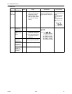
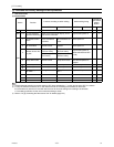
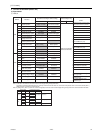
[1] Functions and Factory Settings of the Dipswitches
1. Heat source unit
(1) Control board
1) Unless otherwise specified, leave the switch to OFF where indicated by "-," which may be set to OFF for a reason.
2) A: Only the switch on either the OC or OS needs to be set for the setting to be effective on both units.
B: The switches on both the OC and OS need to be set to the same setting for the setting to be effective.
C: The setting is effective for the unit on which the setting is made.
3) Refer to "VII [2] Controlling the Heat source Unit" for details.(page 143)
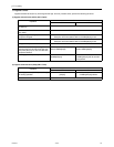
Switch Function
Function according to switch setting Switch setting timing
Units that re-
quire switch
setting
Note.2
OFF ON OFF ON OC OS
SWU 1-2 Unit address setting Set to 00 or 51-100 with the dial switch Before power on C C
SW1 1-10
For self-diagnosis/
operation monitoring
Refer to the LED monitor display on the
heat source unit board.
Anytime after power on
CC
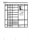
SW2
1
Centralized control
switch
Without connection
to the centralized
controller
With connection to
the centralized con-
troller
Before power on
BB
2
Deletion of connec-
tion information
Normal control Deletion Before power on
A-
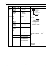
3
Deletion of error his-
tory SW
(OC) Storage of IC/
OC error history
(OC) Deletion of IC/
OC error history
Anytime after power on
(When switched from OFF
to ON)
CC
(OS) Storage of OS
error history
(OS) Deletion of
OS error history
4 Pump down mode Normal control Pump down mode
After being energized and
while the compressor is
stopped
A-
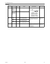
5- - - - --
6- - - - --
7
Power on signal out-
put switch
During Thermo-ON
During Thermo-
OFF
Anytime after power on
A-
8- - - - --
9- - - - --
10 - - - - - -