


95
FX3S/FX3G/FX3GC/FX3U/FX3UC Series
Programming Manual - Basic & Applied Instruction Edition
4 Devices in Detail
4.4 State Relay [S]
1
Introduction
2
Overview
3
Instruction
List
4
Devices
in Detail
5
Specified the
Device &
Constant
6
Before
Programming
7
Basic
Instruction
8
FNC00-FNC09
Program Flow
9
FNC10-FNC19
Move & Compare
10
FNC20-FNC29
Arith. & Logic
Operation
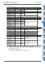
4.4.2 Functions and operation examples
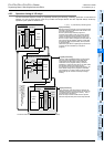
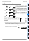
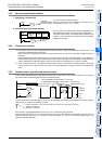
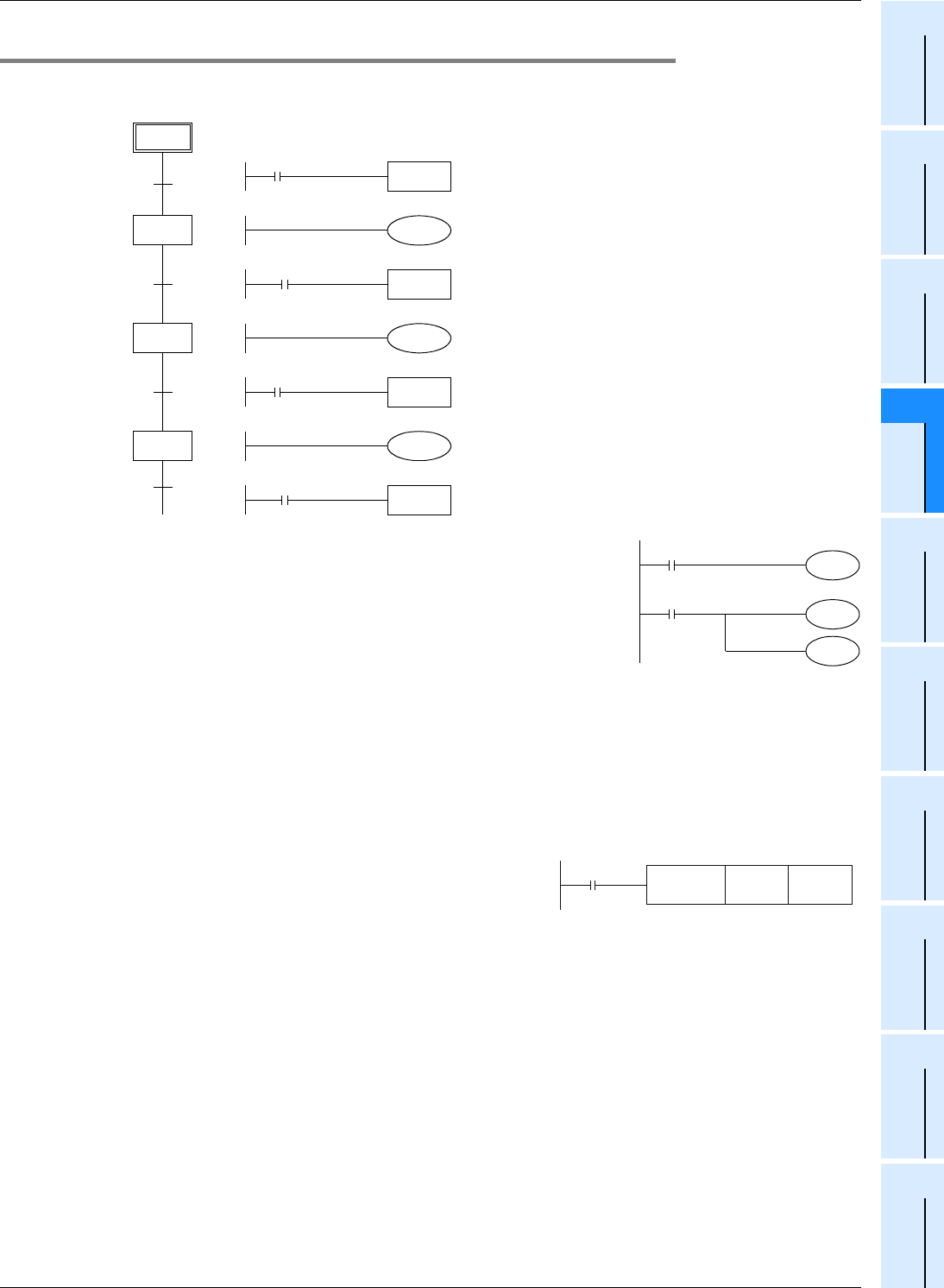
1. General type
In the stepping type process control shown in the left
figure, when the start signal X000 turns ON, the state relay
S20 is set (turned ON) and the solenoid valve Y000 for
moving down turns on.
When the lower limit switch X001 turns ON the state relay
S21 is set (turned ON) and the solenoid valve Y001 for
clamping turns on.
When the clamp confirmation limit switch X002 turns ON,
the state relay S22 is set (turned ON).
When the operation proceeds to the next step, the state
relay in the preceding step is automatically reset (turned
OFF).
When the PLC turns OFF, all of general type state relays
are turned OFF.
When the ON/OFF status just before power failure is
required, use latched (battery backed) type state relays.
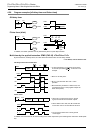
State relays have many NO contacts and NC contacts in the same way as
auxiliary relays, and such contacts can be used arbitrarily in sequence
programs.
When state relays (S) are not used for step ladder instructions, they can be used
in general sequences in the same way as auxiliary relays (M) (as shown in the
figure on the right).
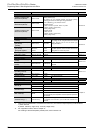
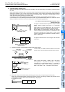
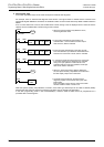
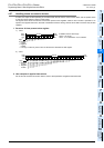
2. Latched (battery backed) type
• Latched (battery backed) type state relays store their ON/OFF status even if the power is shut down while the PLC
is operating, so the operation can be restarted from the last point in the process.
In FX
3U/FX3UC PLCs, latched (battery backed) type devices are backed up by the battery built into the PLC.
In FX
3S/FX3G/FX3GC PLCs, latched type devices are backed up by the EEPROM built into the PLC. When the
optional battery is installed in FX
3G/FX3GC PLCs, the battery backs up some general type devices.
→ For details on backup against power failure, refer to Chapter 2.6.
• When using latched (battery backed) type state relays as general
type state relays, provide a reset circuit shown in the right figure
around the head step in the program.
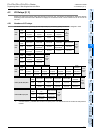
S 2
S 20
S 21
S 22
Start
Lower
limit
Clamping
Upper
limit
Initial state
TRAN
Start
X000
Y000
Moving down
TRAN
Lower limit
X001
Y001
Clamping
TRAN
Clamping
X002
Y002
Moving up
TRAN
Upper limit
X003
X001
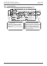
S10
S10
M30
Y005
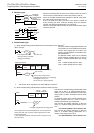
M8002
Initial pulse
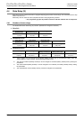
FNC 40
ZRST
S1000 S1200
0
S1000 to S1200 are initialized.
Ex. FX3U/FX3UC PLCs