68
FX3S/FX3G/FX3GC/FX3U/FX3UC Series
Programming Manual - Basic & Applied Instruction Edition
2 Overview (Sequence Program)
2.7 Types and Setting of Parameters
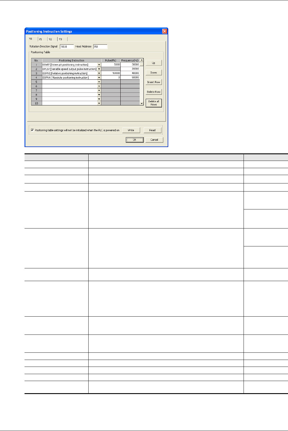
3. Click [Individual setting] button to display Positioning Instruction Settings dialog box.
In this dialog box, set the positioning table for each pulse output destination.
Set item Contents of setting Setting range
Y0 Set the positioning table for the pulse output destination Y000. –
Y1 Set the positioning table for the pulse output destination Y001. –
Y2
*1
Set the positioning table for the pulse output destination Y002. –
Y3
*2
Set the positioning table for the pulse output destination Y003. –
Rotation Direction Signal
Set the relay number of the rotation direction output signal.
Initial setting: Pulse output destination Y000: Y010
Pulse output destination Y001: Y011
Pulse output destination Y002
*1
: Y012
Pulse output destination Y003
*2
: Y013
→Refer to the Positioning Control Manual.
FX3U/FX3UC:
Y000 to Y357
FX3G/FX3GC:
Y000 to Y177
Head Address
Set the head number of devices storing the set data (pulse number and
frequency).
1600 devices (FX3U and FX3UC) or 1200 devices (FX3G and FX3GC) are
occupied starting from the head device number set here regardless of the
number of axes.
Initial setting: R0
→Refer to the Positioning Control Manual.
FX3U/FX3UC:
D0 to D6400
R0 to R31168
FX3G/FX3GC:
D0 to D6400
R0 to R22800
No.
This column shows the table number.
Numbers 1 to 100 can be set.
–
Positioning Instruction
Select the positioning type among the following:
DDVIT (Interrupt positioning instruction)
*3
DPLSV (Variable speed output pulse instruction)
DDRVI (Relative positioning instruction)
DDRVA (Absolute positioning instruction)
→Refer to the Positioning Control Manual.
–
Pulse (Pls)
Set the pulse number output by the operation (instruction) set in "Positioning
Instruction" column.
→Refer to the Positioning Control Manual.
Refer to the
Positioning Control
Manual.
Frequency [Hz]
Set the speed (pulse frequency) output by the operation (instruction) set in
"Positioning Instruction" column.
→Refer to the Positioning Control Manual.
Refer to the
Positioning Control
Manual.
Up This button transposes the selected line to the upper line. –
Down This button transposes the selected line to the lower line. –
Insert Row This button inserts a line in the currently selected position. –
Delete Row This button deletes the currently selected line. –
Delete all Rows
This button deletes the entire setting of the positioning table for the selected
pulse output destination.
–


