


93
FX3S/FX3G/FX3GC/FX3U/FX3UC Series
Programming Manual - Basic & Applied Instruction Edition
4 Devices in Detail
4.3 Auxiliary Relay [M]
1
Introduction
2
Overview
3
Instruction
List
4
Devices
in Detail
5
Specified the
Device &
Constant
6
Before
Programming
7
Basic
Instruction
8
FNC00-FNC09
Program Flow
9
FNC10-FNC19
Move & Compare
10
FNC20-FNC29
Arith. & Logic
Operation
2. Latched (battery backed) type
When the power is turned OFF while the PLC is operating, all of the output relays and general type auxiliary relays
turn OFF.
When restoring the power again, all of the output relays and general type auxiliary relays remain OFF except those
whose input condition is ON. In some output relays and auxiliary relays, however, the ON/OFF status just before
power failure should be stored and then replicated when restoring the power, depending on control targets. In such a
case, use latched (battery backed) type auxiliary relays.
In FX
3U/FX3UC PLCs, latched (battery backed) type devices are backed up by the battery built into the PLC.
In FX
3S/FX3G/FX3GC PLCs, latched type devices are backed up by the EEPROM built into the PLC. When the optional
battery is installed in FX
3G/FX3GC PLCs, the battery backs up some general type devices.
→ For details on backup method against power failure,
refer to Section 2.6.
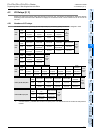
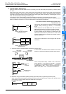
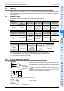
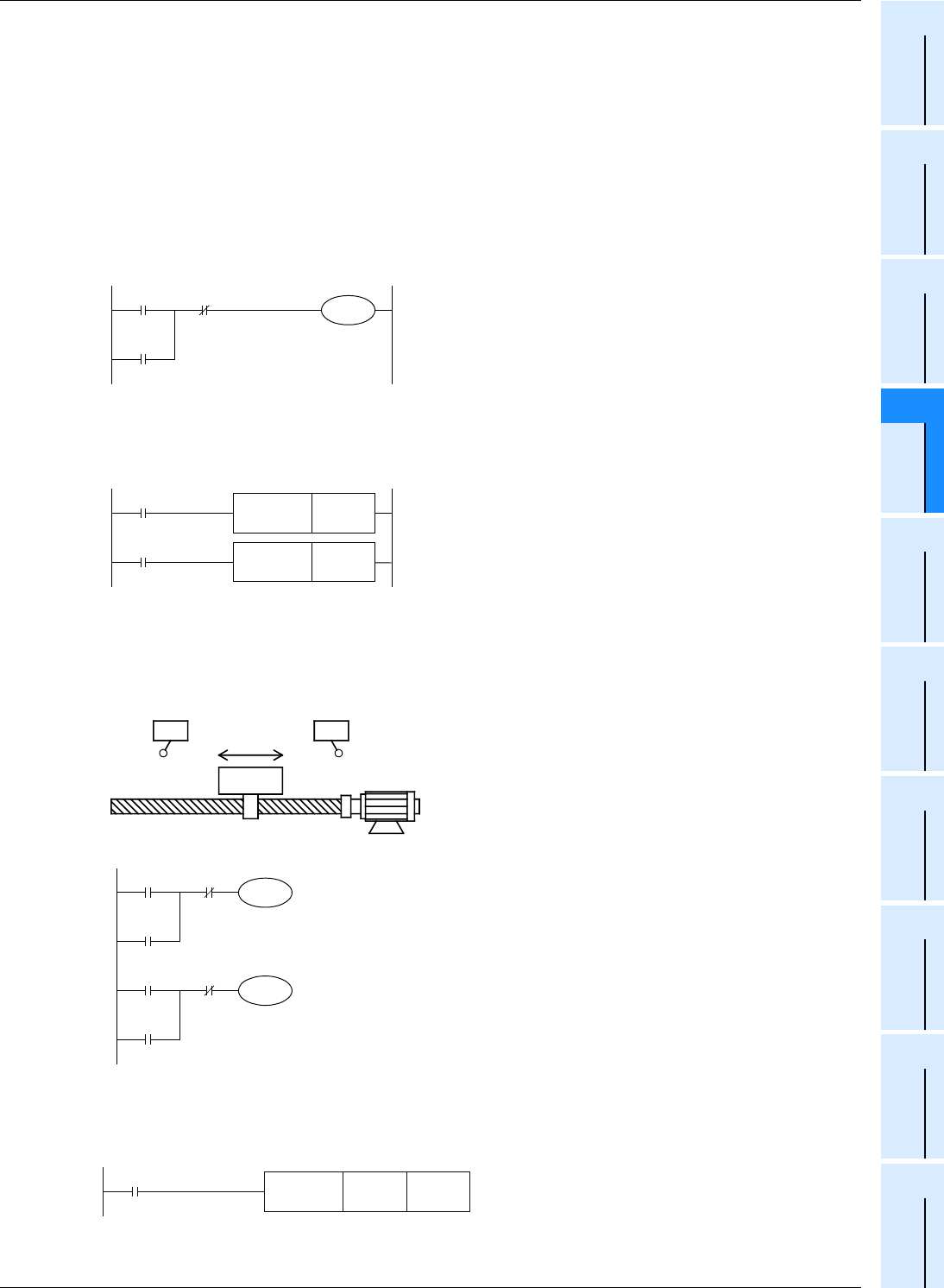
The figure on the left shows an operation example of M600
(latched [battery backed] type device) in a self-holding
circuit.
When X000 turns ON and M600 turns ON in this circuit,
M600 holds its operation by itself even if X000 is opened.
Because M600 is a latched (battery backed) type device, it
remains activated when the operation is restarted even after
X000 has turned OFF due to power failure. If an NC contact
of X001 is opened when the operation is restarted, however,
M600 is deactivated.
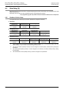
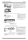
The figure on the left shows a circuit using the SET and RST
instructions.
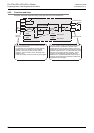
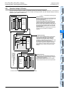
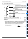
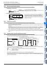
1) Application example of latched (battery backed) type auxiliary relays
In some cases, the table should be restarted in the same
direction as the direction selected just before power failure.
X000 = ON (at the left limit) → M600 = ON→ The table is
driven rightward. → The power is turned OFF. → The table
is stopped in an intermediate position. → The table is
restarted (M600 = ON). → X001 = ON (at the right limit) →
M600 = OFF, M601 = ON → The table is driven leftward.
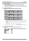
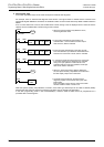
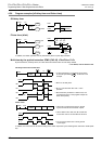
2) Method for using a fixed latched (battery backed) type auxiliary relay as a general type auxiliary relay
When using a fixed latched (battery backed) type auxiliary relay as a general type auxiliary relay, provide a reset
circuit shown in the figure below around the head step in the program.
Ex. FX
3U/FX3UC PLCs
X000
M600
X001
PLC
Backup against power failure
(self-holding circuit)
M600
X000
X001
PLC
Backup against power failure
(set/reset circuit)
SET M600
RST M600
X000
M600
X001
M600
Rightward
drive
command
X001
M601
X000
M601
Leftward drive
command
Left limit
Limit switch
LS1 (X000)
Right limit
Limit switch
LS2 (X001)
Table in reciprocating motion
Motor with brake
M8002
Initial pulse
FNC 40
ZRST
M1024 M1999
M1024 to M1999 are initialized.