


377
FX3S/FX3G/FX3GC/FX3U/FX3UC Series
Programming Manual - Basic & Applied Instruction Edition
13 High-Speed Processing – FNC 50 to FNC 59
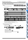
13.8 FNC 57 – PLSY / Pulse Y Output
11
FNC30-FNC39
Rotation and
Shift
12
FNC40-FNC49
Data Operation
13
FNC50-FNC59
High-Speed
Processing
14
FMC60-FNC69
Handy
Instruction
15
FNC70-FNC79
External FX I/O
Device
16
FNC80-FNC89
External FX
Device
17
FNC100-FNC109
Data
Transfer 2
18
FNC110-FNC139
Floating Point
19
FNC140-FNC149
Data
Operation 2
20
FNC150-FNC159
Positioning
Control
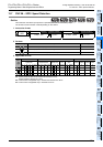
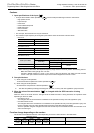
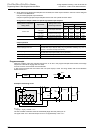
2. Monitoring the current number of generated pulses
The number of pulses output from Y000 or Y001 is stored in the following special data registers:
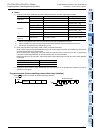
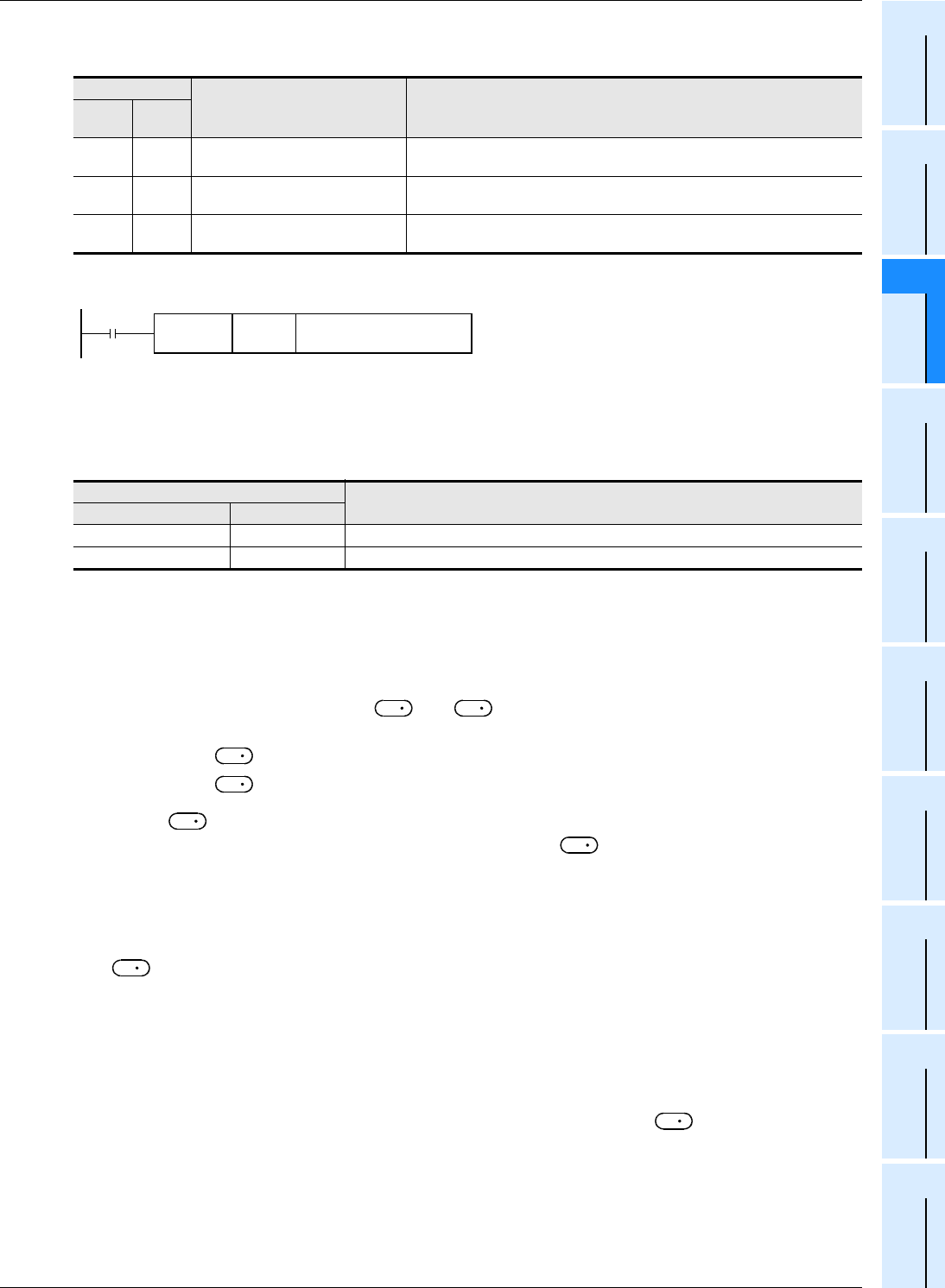
The contents of each data register can be cleared using the following program:
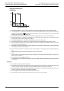
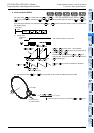
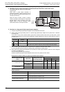
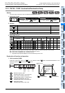
3. How to stop the pulse output
• When the command input is set to OFF, the pulse generation is immediately stopped. When the command input is
set to ON again, pulse generation operation restarts from the beginning.
• When the special auxiliary relays (M) shown below are set to ON, the pulse output is stopped.
To restart pulse output, set the device (FX
3S/FX3G/FX3GC : M8145, M8146, M8349, M8359
FX
3U/FX3UC : M8349, M8359) corresponding to the output signal to OFF, and then drive the pulse output instruction
again.
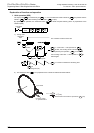
Cautions
1. When a word device is specified as or
When the value of the word device is changed while the instruction is executed, the following operation results:
• When the data in is changed, the output frequency changes accordingly.
• When the data in is changed, the change (new value) becomes valid the next time the instruction is driven.
2. Frequency
When using transistor outputs in the main unit, set the output frequency to "100,000 Hz" or less.
If the load is operated using pulses at a frequency higher than 100,000 Hz, the PLC may be damaged.
Do not set the output frequency to "0".
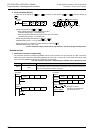
3. Pulse output
• Only a transistor output on the main unit or Y000 or Y001 on a special high-speed output adapter
*1
can be specified
in .
When using the PLSY (FNC 57) instruction with a relay output type or triac output type FX
3U PLC, a special high-
speed output adapter is required.
*1. High-speed output special adapters can be connected only to FX
3U PLC.
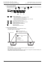
• The duty cycle of the pulse ON/OFF time is 50 % inside the PLC.
However, 50 % may not be output depending on the frequency due to the effect of the output circuit.
• The pulse output is controlled by the dedicated hardware not affected by the sequence program (operation cycle).
• If the command input is set to OFF during continuous pulse output, the output from turns OFF.
Device
Description Contents of data
High
order
Low
order
D8141 D8140
Accumulated number of pulses
output from Y000
Accumulated number of pulses output from Y000 by PLSY and PLSR
instructions
D8143 D8142
Accumulated number of pulses
output from Y001
Accumulated number of pulses output from Y001 by PLSY and PLSR
instructions
D8137 D8136
Total accumulated number of
pulses output from Y000 and Y001
Total accumulated number of pulses output from Y000 and Y001 by PLSY and
PLSR instructions
Device
Description
FX3S/FX3G/FX3GC FX3U/FX3UC
M8145, M8349 M8349 Immediately stops pulse output from Y000.
M8146, M8359 M8359 Immediately stops pulse output from Y001.
FNC 12
DMOV
K0
Low-order device shown in
table above
Command
input
S
1
S
2
S
1
S
2
S
1
S
1
D
D