


820
FX3S/FX3G/FX3GC/FX3U/FX3UC Series
Programming Manual - Basic & Applied Instruction Edition
36 Interrupt Function and Pulse Catch Function
36.8 Pulse width/Pulse period measurement function [M8075 to M8079, D8074 to D8097]
36.8 Pulse width/Pulse period measurement function [M8075 to M8079, D8074
to D8097]
The pulse width/pulse period measurement function stores the values of 1/6 µs ring counters at the input signal rising
edge and falling edge to special data registers. This function also divides by "60" the difference in the counter value
(pulse width) between the rising edge and the falling edge or the difference in the counter value (pulse period)
between the previous rising edge and the current rising edge, and stores the obtained pulse width or pulse period in
units of 10 µs to special data registers.
The pulse width/pulse period measurement function becomes valid when a program is described using M8075 as a
contact. Specify the pulse width measurement flag in the subsequent OUT instruction, and set an input terminal to be
used.
When the pulse width/pulse period measurement function is valid, it always operates while the PLC mode is RUN.
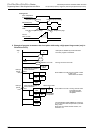
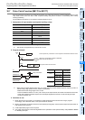
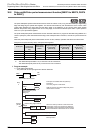
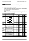
Assignment of special auxiliary relays and special data registers
*1. Cleared when the PLC mode switches from STOP to RUN.
*2. The measurable pulse width is 10 µs minimum and 100 s maximum.
The measurable pulse period is 20 µs minimum and 100 s maximum.
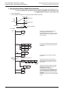
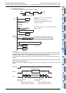
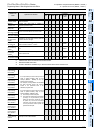
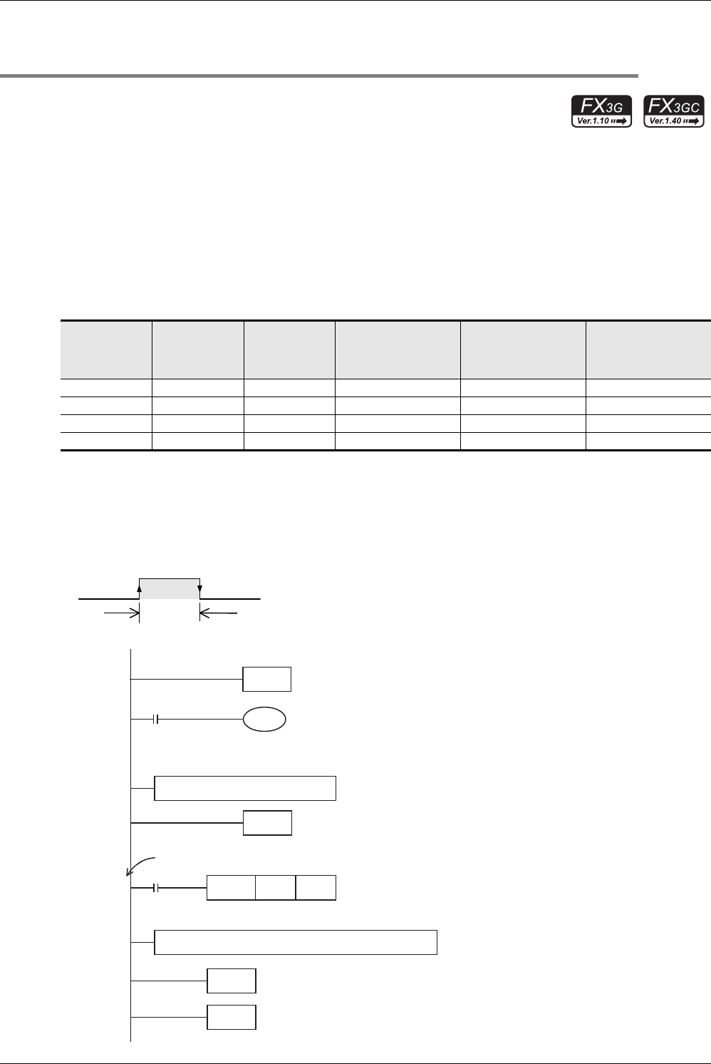
1. Program example
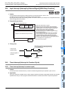
1) Pulse width measurement
The pulse width of the input signal from X000 is measured.
Pulse input
Pulse width/
Pulse period
measurement
flag
Pulse period
measurement
mode
*1
Ring counter value
for rising edge
*1
[Unit: 1/6 µs]
Ring counter value
for falling edge
*1
[Unit: 1/6 µs]
Pulse width
/Pulse period
*1*2
[Unit: 10 µs]
X000 M8076 M8080 D8075,D8074 D8077,D8076 D8079,D8078
X001 M8077 M8081 D8081,D8080 D8083,D8082 D8085,D8084
X003 M8078 M8082 D8087,D8086 D8089,D8088 D8091,D8090
X004 M8079 M8083 D8093,D8092 D8095,D8094 D8097,D8096
This duration is measured.
X000
OFF
ON
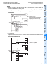
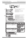
FNC 04
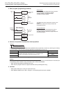
EI
FNC 03
IRET
END
Step
0
FNC 06
FEND
User program
I000
interrupt
pointer
X000 Falling edge interrupt
Interrupt return
Interrupts are enabled after EI (FNC 04)
instruction.
The main program is described.
X000 is used for the pulse width/pulse period
measurement function.
When the interrupt routine is executed at the
falling edge of the input signal from X000, the
pulse width of input signal from X000 stored in
D8078 and D8079 is transferred to D1 and D0.
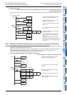
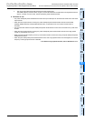
M8075
M8000
RUN monitor
FNC 12
DMOV
D8078 D0
User program (Interrupt at the falling edge(X000))
Pulse width/Pulse period
measurement
setting flag
M8076