


435
FX3S/FX3G/FX3GC/FX3U/FX3UC Series
Programming Manual - Basic & Applied Instruction Edition
15 External FX I/O Device – FNC 70 to FNC 79
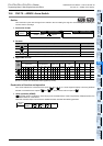
15.5 FNC 74 – SEGL / Seven Segment With Latch
11
FNC30-FNC39
Rotation and
Shift
12
FNC40-FNC49
Data Operation
13
FNC50-FNC59
High-Speed
Processing
14
FMC60-FNC69
Handy
Instruction
15
FNC70-FNC79
External FX I/O
Device
16
FNC80-FNC89
External FX
Device
17
FNC100-FNC109
Data
Transfer 2
18
FNC110-FNC139
Floating Point
19
FNC140-FNC149
Data
Operation 2
20
FNC150-FNC159
Positioning
Control
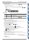
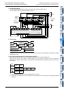
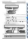
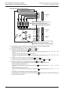
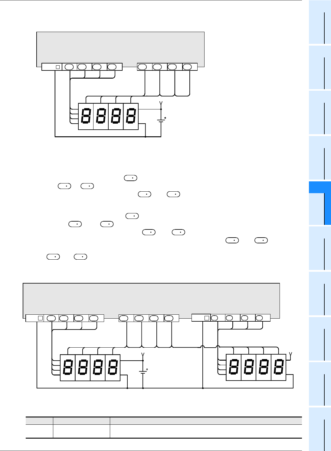
3) Example of connecting one seven-segment display unit
The figure below shows an example of the FX
3U series main unit (sink output).
For wiring details, refer to the Hardware Edition of each PLC.
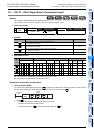
When using two sets of 4 digits (n = K4 to K7)
→ For selection of "n", refer to Subsection 15.5.2.
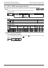
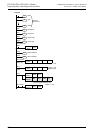
1) Data and strobe signal
a) 1st set of 4 digits
A 4-digit numeric value stored in is converted from binary into BCD, and its each digit is output in turn
from to +3 by the time division method.
The strobe signal is output in turn from +4 to +7 by the time division method also to latch the first
set of 4-digit seven-segment display unit.
b) 2nd set of 4 digits
A 4-digit numeric value stored in +1 is converted from binary into BCD, and its each digit is output in
turn from +10 to +13 by the time division method.
The strobe signal is output in turn from +4 to +7 by the time division method also to latch the
second set of 4-digit seven-segment display unit. (The strobe signal outputs +4 to +7 are shared
by the 1st and 2nd sets.)
2) For and +1, binary data ranging from 0 to 9999 is valid.
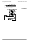
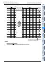
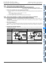
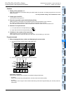
3) Example of connecting two seven-segment display units
The figure below shows an example of the FX
3U series main unit (sink output).
For wiring details, refer to the Hardware Edition of each PLC.
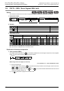
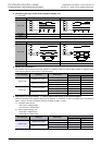
Related devices
→ For the instruction execution complete flag use method, refer to Subsection 6.5.2.
Device Name Description
M8029
Instruction execution com-
plete flag
Turns ON when output of 4 digits is finished.
10
0
4
2
81
1
2
4
8
1st set
V+
10
1
10
2
10
3
10
3
10
2
10
1
10
0
COM
+1 +2 +3 +4 +6 +7
+5
PLC (transistor output type)
D
D
D
D
D
D
D
D
S
D
D
D
D
S
D
D
D
D
D
D
S
S
10
0
4
2
81
1
2
4
8
1st set
V+
10
1
10
2
10
3
10
3
10
2
10
1
10
0
COM +1
PLC
(transistor output type)
+2 +3 +4 +6 +7
+5
D
D
D
D
D
D
D
D
2nd set
V+
1
2
4
8
4
2
81
10
3
10
2
10
1
10
0
+10 +11 +12 +13
D
D
D
D
COM