664
FX3S/FX3G/FX3GC/FX3U/FX3UC Series
Programming Manual - Basic & Applied Instruction Edition
29 Data Table Operation – FNC250 to FNC269
29.2 FNC257 – BAND / Dead Band Control
29.2 FNC257 – BAND / Dead Band Control
Outline
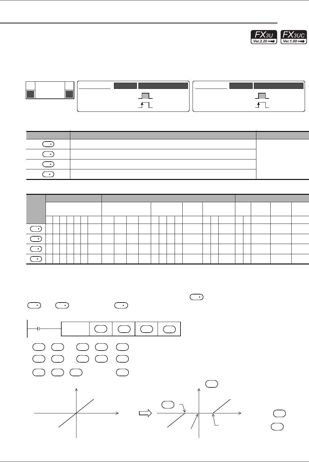
This instruction provides the upper limit value and lower limit value of the dead band for an input numeric value, and
controls the output value using these limit values.
1. Instruction format
2. Set data
3. Applicable devices
Explanation of function and operation
1. 16-bit operation (BAND and BANDP)
Depending on how the input value (16-bit binary value) specified by compares to the dead band range between
and , the output value is controlled.
Operand Type Description Data Type
Lower limit value of the dead band (no-output band)
16- or 32-bit binary
Upper limit value of the dead band (no-output band)
Input value controlled by the dead band
Device number storing the output value controlled by the dead band
Oper-
and
Type
Bit Devices Word Devices Others
System User Digit Specification System User
Special
Unit
Index
Con-
stant
Real
Number
Charac-
ter String
Pointer
XYMTCSD
.b KnX KnY KnM KnS T C D R
U\G
V Z Modify K H E "
"P
P
FNC 257
BAND
D
Mnemonic Operation Condition
16-bit Instruction
9 steps
BAND
BANDP
Mnemonic Operation Condition
Continuous
Operation
Pulse (Single)
Operation
32-bit Instruction
17 steps
DBAND
DBANDP
Continuous
Operation
Pulse (Single)
Operation
S
1
S
2
S
3
D
S
1
S
2
S
3
D
S
3
S
1
S
2
D
"
≤
≤
" ............0
→
FNC257
BAND
Output
( )
Lower limit value of
dead band
S1
S2
D
S3
Input
value
Output value
Command
input
" > " .... -
→
" < " .... -
→
D
Output value ( )
Output
D
Input value ( )
S3
S1
Upper limit value of
dead band
( )
S2
Output value = 0
S3
S
1
S
3
S
1
DS
3
S
2
S
3
S
2
DS
3
S
1
S
2


