


430
FX3S/FX3G/FX3GC/FX3U/FX3UC Series
Programming Manual - Basic & Applied Instruction Edition
15 External FX I/O Device – FNC 70 to FNC 79
15.3 FNC 72 – DSW / Digital Switch (Thumbwheel Input)
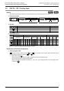
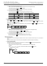
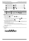
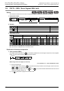
2) Specification of the number of sets ("n")
- When using one set of 4 digits [n = k1]
A 4-digit BCD digital switch connected to to +3 is read in turn by the strobe signal to
+3, and stored in binary format to .
- When using two sets of 4 digits [n = k2]
A 4-digit BCD digital switch connected to to +3 is read in turn by the strobe signal to
+3, and stored in binary format to .
A 4-digit BCD digital switch connected to +4 to +7 is read in turn by the strobe signal to
+3, and stored in binary format to +1.
Related devices
→ For the instruction execution complete flag use method, refer to Subsection 6.5.2.
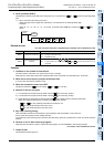
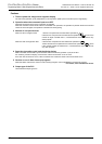
Cautions
1. When the command contact turns OFF
Though the contents of do not change, all of to +3 turn OFF.
2. Number of occupied devices
1) When two sets of 4 digits (n = K2) are used, two devices are occupied starting from .
2) When one set of 4 digits is used, four devices are occupied starting from . When two sets of 4 digits are
used, eight devices are occupied starting from .
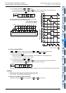
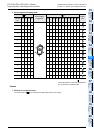
3. When connecting a digital switch of up to 3 digits
It is not necessary to wire the strobe signal (output for digit specification) to unused digits. Because unused
digits are occupied also by this instruction, however, they cannot be used for any other purpose. Make sure to leave
unused outputs are left vacant.
4. Transistor output type is recommended
For continuously receiving digital switch values, make sure to use a transistor output type PLC.
→ For a relay type PLC, refer to "4. How to use this instruction in a relay output type PLC" later.
5. Digital switches
Use BCD output type digital switches.
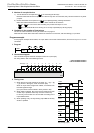
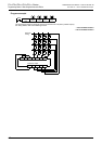
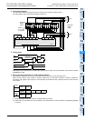
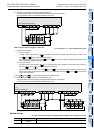
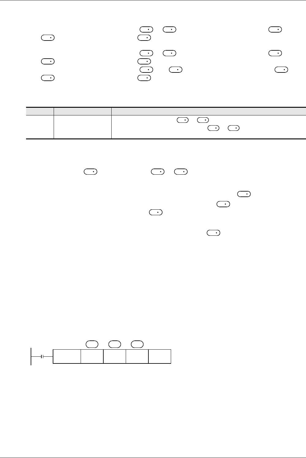
Program example
In the program example shown below, digital switches are connected to inputs starting from X010 and outputs from
Y010.
1. Program
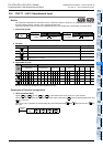
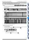
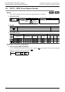
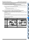
Device Name Description
M8029
Instruction execution com-
plete flag
OFF: Data is being output to to +3 or the instruction is not executed yet.
ON: A cycle operation of outputting data to to +3 (scan of the 1st to 4th digits)
is completed.
S
S
D
1
D
1
D
2
S
S
D
1
D
1
D
2
S
S
D
1
D
1
D
2
D
1
D
1
D
1
D
1
D
2
D
1
D
1
D
2
S
S
D
1
X000
FNC 72
DSW
X010 Y010 D 0 K 1
n
D
1
S
D
2