


3. MOUNTING AND WIRING
3
−
7
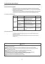
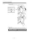
3.4 Mounting the Serial Absolute Synchronous Encoder
Precautions when using a MR-HENC serial absolute synchronous encoder.
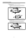
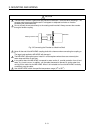
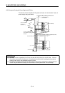
(1) If the serial absolute synchronous encoder is linked to a chain, timing belt, or
gears, the machine rotating shaft should be supported by a separate bearing
and connected to MR-HENC through a coupling. Ensure that excessive force
(greater than the permitted shaft load) is not applied to the encoder.
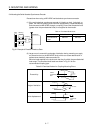
Table 3.1 Permitted Shaft Loads
Radial Direction Thrust Direction
Permitted shaft
load
98N max. 49N max.
Coupling
Bearing
Gear
MR-HENC
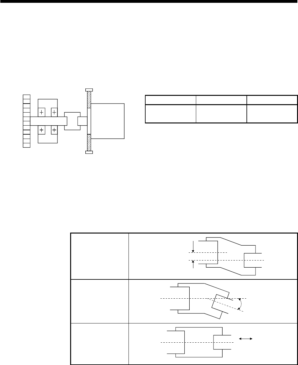
Fig. 3.1 Example of Encoder Linked to a Gear
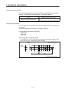
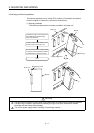
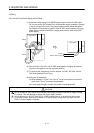
(2) Large errors in eccentricity and angle of deviation during mounting can apply
an excessive force to the MR-HENC shaft, which can cause deterioration in
performance drastically reduce encoder life.
Minimize loads applied to the shaft such that they lie within the permitted shaft
load range. The permitted shaft loads are shown in Fig. 3.2 for the
recommended coupling type.
Table 3.2 Permitted Values for Coupling Mounting Errors
Eccentricity
0.2mm
(0.008 inch)
max.
Angle of deviation
1.5° max.
Axial displacement
0.5mm
(0.02 inch)
max.