


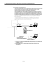
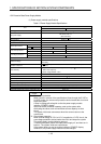
1. SPECIFICATIONS OF MOTION SYSTEM COMPONENTS
1
−
32
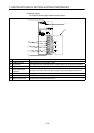
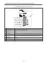
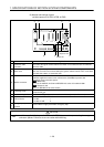
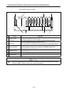
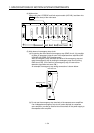
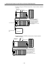
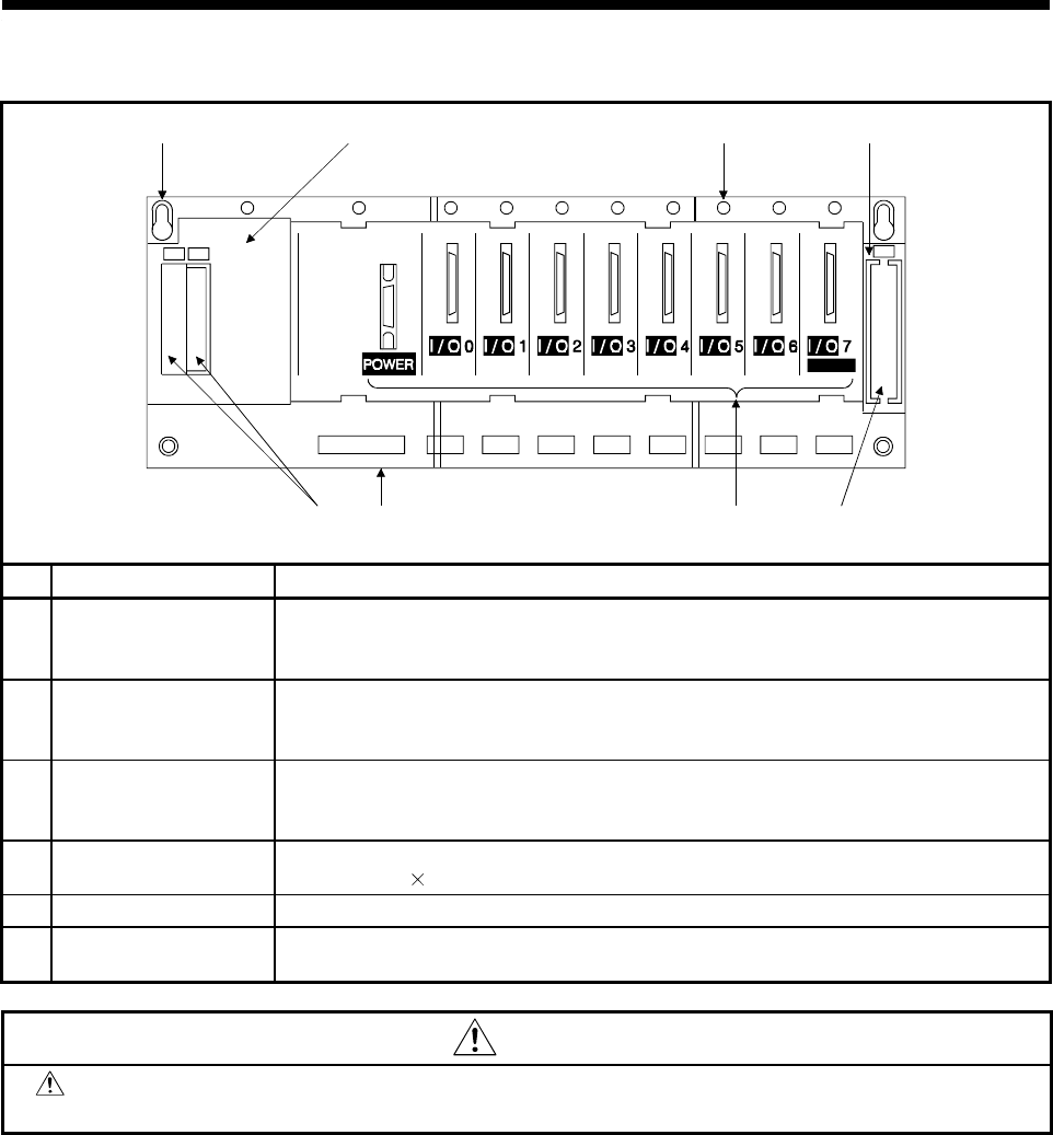
(d) Extension base unit (A168B)
A168B
IN
OUT
OUT
5) 2) 4)
6)1) 3)
*1
1)
2)
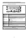
No. Name Application
1)
Extension cable
connector
Connects to the signal communications connector on the main base unit or bus
coupling type GOT with the extension cable.
Take off the supplied connector cover before connecting the extension cable.
2) Base cover
A cover for protecting the extension cable connector.
When connecting to bus coupling type GOT, cut out the area surrounded by the groove
under the word “OUT” on the base cover with side cutters, or other appropriate tool.
3) Module connector
Connectors to mount the Power module, I/O module, and special-function modules.
Install the supplied connector cover or blank cover (A1SG60) to prevent dust
penetrating empty connector spaces.
4) Unit fixing screw
Screws to fix the unit to the base.
Screw size M4
12.
5) Base mounting hole
Slots for mounting the base unit onto the control board panel (for M5 screws).
6) DIN rail hooks
Hooks to attach to the DIN rail.
A168B........................2
CAUTION
*1 : Install the supplied blind cap or blank cover (A1SG60) to prevent dust penetrating the empty
connector spaces. Failure to do so may cause malfunctioning.