


1. SPECIFICATIONS OF MOTION SYSTEM COMPONENTS
1
−
47
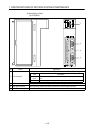
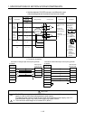
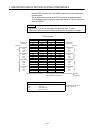
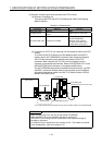
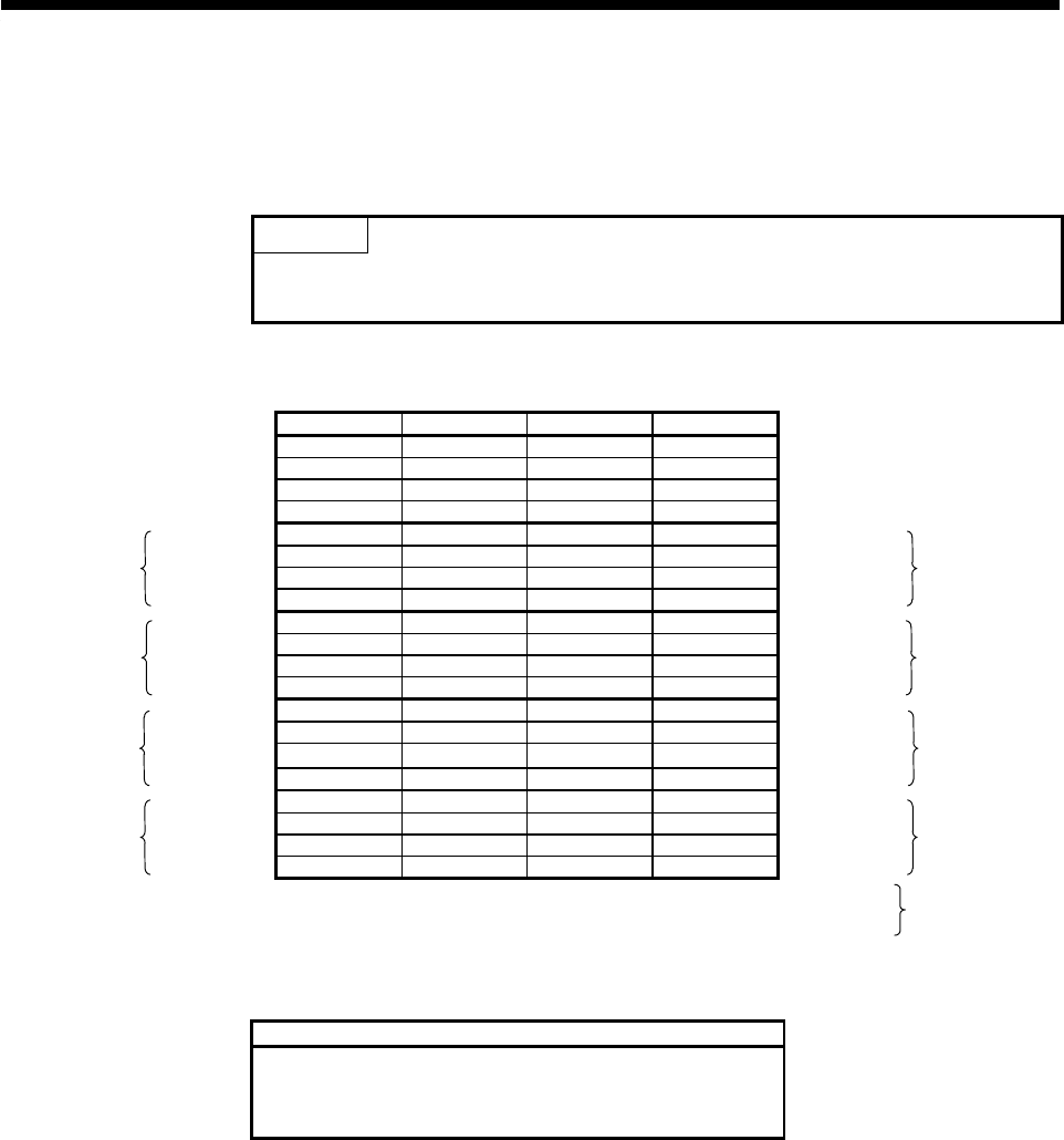
Use the CTRL connector at the A172SENC module front to connect the servo
external signals.
The pin layout and connection of the CTRL connector are described below.
The following pin layout is the front view as seen from the CTRL connector front
of the A172SENC.
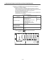
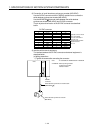
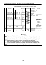
POINT
Signal No.s 1 to 8 can be assigned to the specified axes. To make
assignment, make the system settings of the positioning software package.
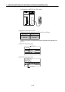
CTRL connector
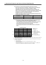
PIN No. Signal Name PIN No. Signal Name
A1 BRK.COM B1 COM
A2 BRK B2 COM
External input
signal name
A3 Vacant B3 Vacant
External input
signal name
Signal No. A4 Vacant B4 TRA Signal No.
DOG/CHANGE A5 PX1F B5 PXF DOG/CHANGE
STOP A6 PX1E B6 PXE STOP
8
RLS A7 PX1D B7 PXD RLS
4
FLS A8 PX1C B8 PXC FLS
DOG/CHANGE A9 PX1B B9 PXB DOG/CHANGE
STOP A10 PX1A B10 PXA STOP
7
RLS A11 PX19 B11 PX9 RLS
3
FLS A12 PX18 B12 PX8 FLS
DOG/CHANGE A13 PX17 B13 PX7 DOG/CHANGE
STOP A14 PX16 B14 PX6 STOP
6
RLS A15 PX15 B15 PX5
RLS
2
FLS A16 PX14 B16 PX4 FLS
DOG/CHANGE A17 PX13 B17 PX3 DOG/CHANGE
STOP A18 PX12 B18 PX2 STOP
5
RLS A19 PX11 B19 PX1 RLS
1
FLS A20 PX10 B20 PX0 FLS
Applicable connector model name.......FCN-361J040-AU connector (manufactured by Fujitsu)
FCN-360C040-B connector cover
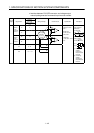
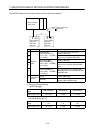
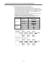
DOG/CHANGE, STOP, RLS, FLS functions of each axis (1 to 8)
DOG/CHANGE............Near-zero point dog/speed-position change signal
STOP ..........................Stop signal
RLS .............................Lower stroke limit
FLS..............................Upper stroke limit
For signal details, refer to the
programming manual.
(Standard
accessories)