


1. SPECIFICATIONS OF MOTION SYSTEM COMPONENTS
1
−
34
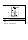
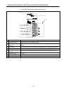
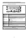
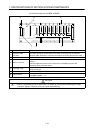
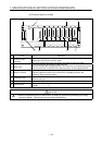
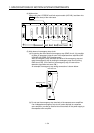
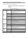
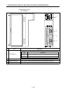
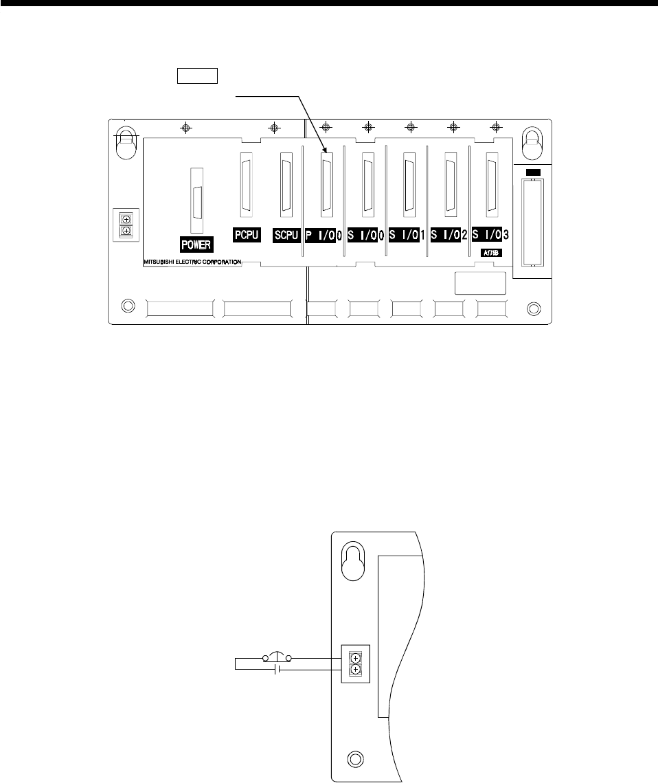
(4) Motion slots
When using the A172SENC and limit output module (A1SY42), load them into
P I/O
(motion slots) of the main base.
OUT
Motion slot
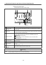
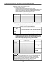
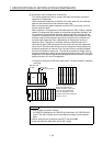
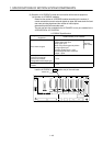
(5) Main base unit emergency stop circuit
(a) By opening the main base unit emergency stop (EMG) circuit, it is possible
to effect an emergency stop all axes of the separate servo amplifiers (MR-
H-BN/MR-J2S-B/MR-J2-B) simultaneously.
After an emergency stop, eliminate the cause of the emergency stop and
reset the emergency stop by closing the emergency stop circuit (turning
EMG circuit ON). (In the event of an emergency stop, the servo error
detection signal does not come ON.)
An example of emergency stop wiring connections is shown below.
Emergency stop
24VDC
Main base unit
EMG
EMG.COM
(b) Do not use the emergency stop terminals of the separate servo amplifiers.
If an independent emergency stop circuit is also required at a separate
servo amplifier, provide an external circuit that shuts off the power supply to
the separate servo amplifier.