


3. MOUNTING AND WIRING
3
−
11
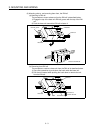
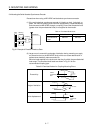
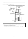
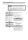
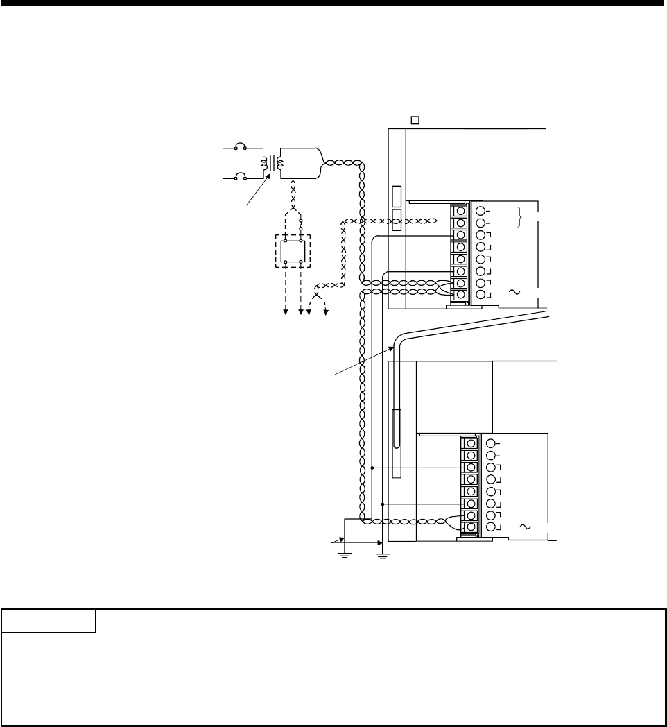
3.5.2 Example of Routing the Power Supply and I/O Wires
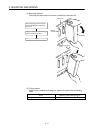
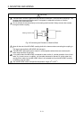
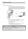
This section shows examples of wiring the main base unit and extension base unit
power-supply and ground wires.
+24V
-24G
FG
LG
INPUT
(Only A171SHCPUN)
(A17 B, A178B(-S1/S2/S3)) main base unit
(A1S65B, A1S68B, A168B) extension base unit
A1S61PN
CPU module
I/O
FG
LG
INPUT
100 200VAC
Extension cable
Connect to 24VDC terminals
of I/O modules requiring 24VDC
internally.
S
elect transformer
a
ccording to
S
ection 3.5.1(c)
AC
100/110VAC
Fuse
AC
DC
24VDC
24VDC
100/110VAC
Ground wire
Ground wire
NC
NC
100 200VAC
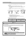
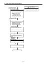
POINTS
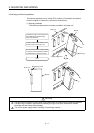
(1) Use wires as thick as possible (2 mm
2
max.) for the 100 VAC, 200 VAC, 24 VDC wires. Twist the
wires when connected to the terminals. Use solderless terminals with insulating tubes to prevent
shorting if the screw in the solderless terminal is loose.
(2) Grounding is required if the FG and LG terminals are connected or resistance to noise is reduced.
A shock may be felt when touching the LG terminal as it has a potential of 1/2 input voltage.