


1. SPECIFICATIONS OF MOTION SYSTEM COMPONENTS
1
−
48
•
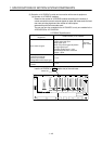
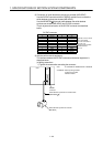
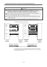
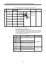
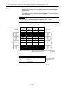
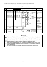
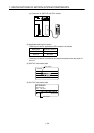
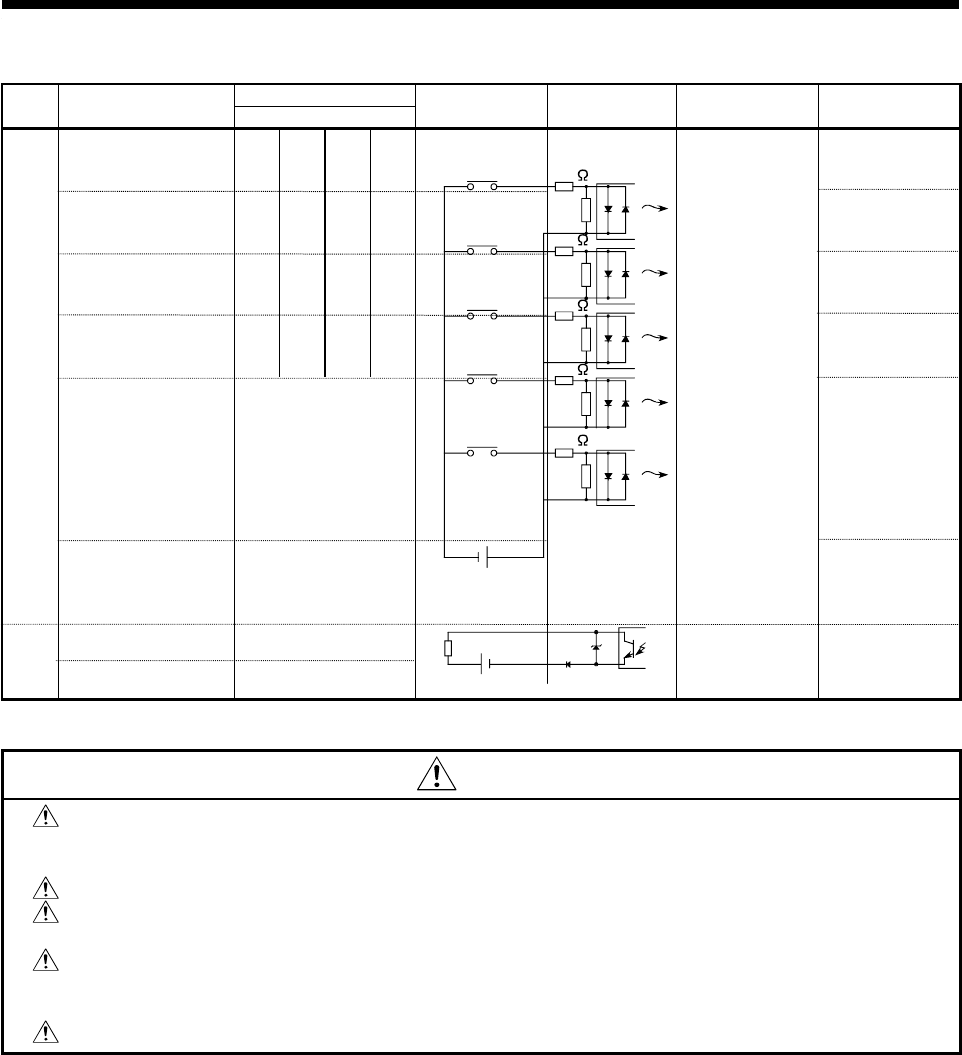
Interface between CTRL connector and servo external signal
Pin Number
Input or
Outpu
t
Signal Name
CTRL Connector
Wiring Example Internal Circuit Specification Description
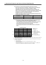
PX0, PX4, PX8, PXC
PX10, PX14, PX18, PX1C
B20
A20
B16
A16
B12
A12
B8
A8
FLS
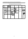
PX1, PX5, PX9, PXD
PX11, PX15, PX19, PX1D
B19
A19
B15
A15
B11
A11
B7
A7
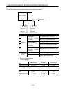
RLS
PX2, PX6, PXA, PXE
PX12, PX16, PX1A, PX1E
B18
A18
B14
A14
B10
A10
B6
A6
STOP
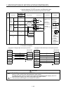
PX3, PX7, PXB, PXF
PX13, PX17, PX1B, PX1F
B17
A17
B13
A13
B9
A9
B5
A5
DOG/CHANGE
TRA B4
Tracking enable
signal input.
•
Generates
interrupts to
A173UHCPU/
A172SHCPUN/
A171SHCPUN.
•
Starts counter
operation.
Input
Power B1 B2
Upper stroke
limit input
Near point DOG/
speed-position
changeover
command
TRA signal
+
-
5VDC to
24VDC
6.8k
Stop signal
input
Lower stroke
limit input
6.8k
6.8k
6.8k
6.8k
•
Supply voltage
12 to 24 VDC
(10.2 to 26.4 VDC,
stabilized power
supply)
•
HIGH level
7.0 VDC
min./1.0mA min.
•
LOW level
1.8 VDC max./0.2
mA max.
Common terminals
for motion control
signals, external
signal and TRA.
BRK A2
Output
BRK, COM A1
24VDC
-
+
Brake
Rated load voltage
24 VDC (21.6 to 30
VDC), 0.1 mA max.
Brake signal output
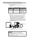
CAUTION
Always use a shielded cable for connection of the SY.ENC connector and external equipment,
and avoid running it close to or bundling it with the power and main circuit cables to minimize the
influence of electromagnetic interference. (Separate them more than 200mm (0.66 inch) away.)
Connect the shield wire of the connection cable to the FG terminal of the external equipment.
Make parameter setting correctly. Incorrect setting may disable the protective functions such as
stroke limit protection or may not provide the brake output, damaging the module.
Always wire the cables when power is off. Not doing so can damage the output circuit if any of
the output signal cables makes contact with the power supply or the output signal cables make
contact with each other.
Use extreme care when wiring the cables. Wrong wiring can damage the internal circuitry.