


1. SPECIFICATIONS OF MOTION SYSTEM COMPONENTS
1
−
5
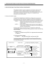
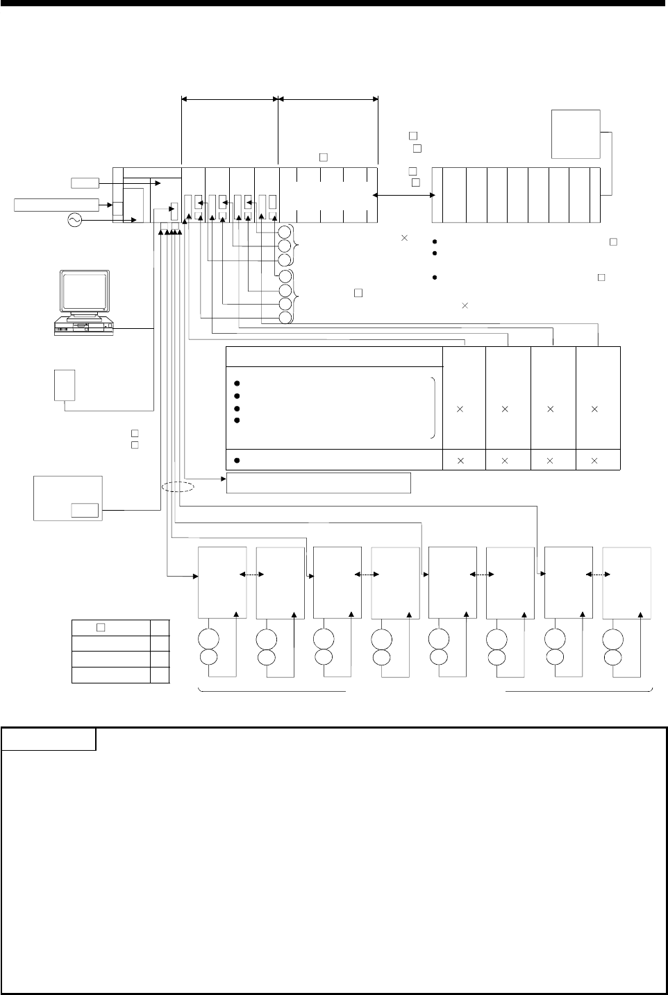
1.2.2 A173UHCPU System Overall Configuration
Motion slot Sequence module slot
Manual pulse
generator/
synchronous encoder
interface module
Battery
Emergency stop input
Power supply
module
Main base unit
(A178B-S3/
A178B-S2/
A178B-S1/
A17 B)
IBM PC
(DOS)
Manual pulse generator 3
(MR-HDP01)
Teaching unit
A31TU-E/A30TU-E
External input signals
SSC I/F card/board
(A30CD-PCF/A30BD-PCF)
Electromagnetic brake command output
SSCNET cable
A6BAT
100/200VAC
A173UHCPU
A172
SENC
P
E
Serial absolute synchronous
encoder cable
(MR-HSCBL M)
Serial absolute synchronous encoder 4
(MR-HENC)
TRA tracking
FLS upper stroke limit
RLS lower stroke limit
STOP signal
DOG/CHANGE near-zero point dog/
speed-position change
8
RS422
RS422
IBM PC (DOS,Windows)
SSCNET4
SSCNET1
d1
d8
M
E
M
E
MR-H-BN/MR-J2S-B/MR-J2-B model
Servo amplifier, max. 32 axes
1
Extension cable
(A1SC B for
A1S6 B
and A168B)
(A1S NB
for A6 B)
Sequence extension base
Up to one extension base unit for A1S6 B
Up to one extension base unit for A168B
(GOT compatible)
Up to one extension base unit for A6 B
GOT
*1
A172
SENC
A172
SENC
A172
SENC
A1S input module or
special function module
*1:No. of motion slots
A17 B 1
A178B-S1 2
A178B-S2 4
A178B-S3 8
*2
d9
d16
M
E
M
E
d17
d24
M
E
M
E
d25
d32
M
E
M
E
SSCNET2
SSCNET3
SSCNET4
*2
8 8 8
P
P
E
E
E
Communication cable
(A270CDCBL M/
A270BDCBL M)
1 1 1
*3
SSCNET:Servo S
y
stem Controller NETwork
POINTS
(1) When using the sequence extension base and bus connection type GOT, select the A168B as the
sequence extension base. When not using the sequence extension base, you can connect the bus
connection type GOT directly to the extension connector of the main base unit.
(2) When using a teaching unit A31TU-E with a dead-man switch, a dedicated connecting cable
A31TUCBL03M is required between the CPU unit and A31TU-E connector. If the A31TU-E is
connected directly to the RS422 connector of the CPU without using a dedicated cable, the
A31TU-E will not operate at all. After disconnecting the A31TU-E, attach a short-circuit connector
A31SHORTCON for A31TUCBL.
(3) In a motion module, a sequence A1S I/O modules can also be installed.
*2 The A173UHCPU can use four channels of the SSCNET. When using the SSCNET card/board
(A30CD-PCF/A30BD-PCF), connect it to the SSCNET4 and the servo amplifiers to the SSCNET1
to 3.
In this case, up to 24 axes of servo amplifiers can be connected.
*3 TRA tracking enable can use any one point.