


1. SPECIFICATIONS OF MOTION SYSTEM COMPONENTS
1
−
54
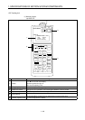
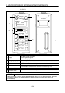
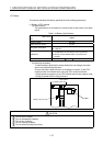
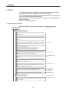
(2) Connection of CPU module and servo amplifiers
This section explains how to connect the CPU module.
Use the SSCNET to connect the CPU module and servo amplifiers. When
using the A172SHCPUN/A171SHCPUN, only one line of SSCNET is available
for servo amplifier connection (use SSCNET1). The A173UHCPU can use up
to four lines for servo amplifier connection. One line of SSCNET allows
connection of up to eight servo amplifies.
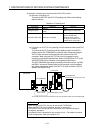
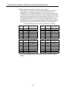
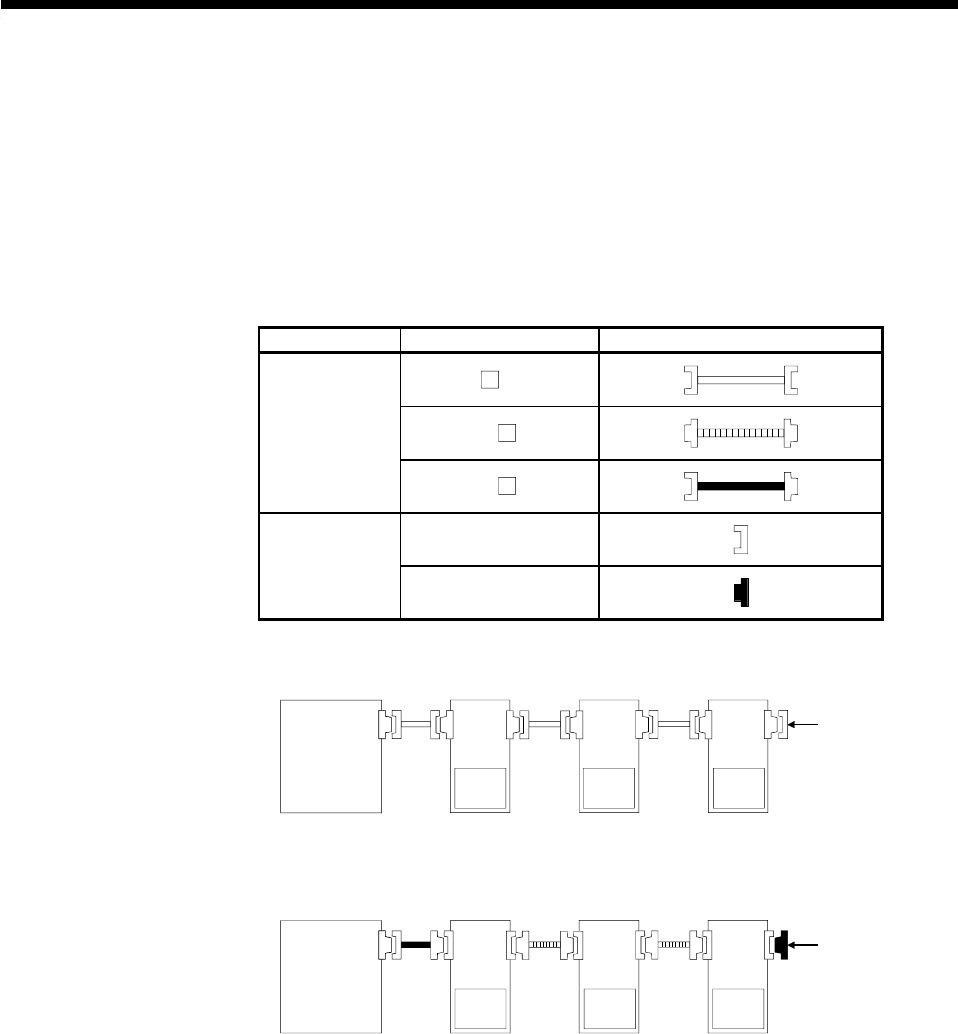
As the SSCNET cables and termination connector used depend on the servo
amplifiers, refer to the following connection example.
The SSCNET cables and termination connector used in the connection
example are any of the models shown in the following table.
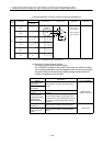
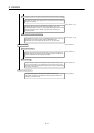
Name Model Name Depiction in Connection Example
MR-HBUS M
MR-J2HBUS MSSCNET cable
MR-J2HBUS
M-A
MR-TM
Termination
connector
MR-A-TM
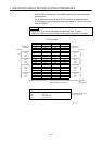
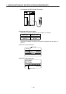
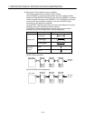
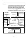
(a) MR-H-BN configuration
CPU module MR-H-BN MR-H-BN MR-H-BN
Battery
MR-BAT,
A6BAT
Termination
connector
Battery
MR-BAT,
A6BAT
Battery
MR-BAT,
A6BAT
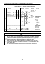
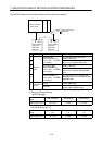
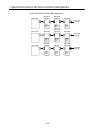
(b) MR-J2S-B/MR-J2-B configuration
Termination
connector
MR-J2S-B
/MR-J2-B
Battery
MR-BAT,
A6BAT
CPU module
Battery
MR-BAT,
A6BAT
Battery
MR-BAT,
A6BAT
MR-J2S-B
/MR-J2-B
MR-J2S-B
/MR-J2-B