3. MOUNTING AND WIRING
3
−
9
3.5 Wiring
3.5.1 How to Run the Power Supply and I/O Wires
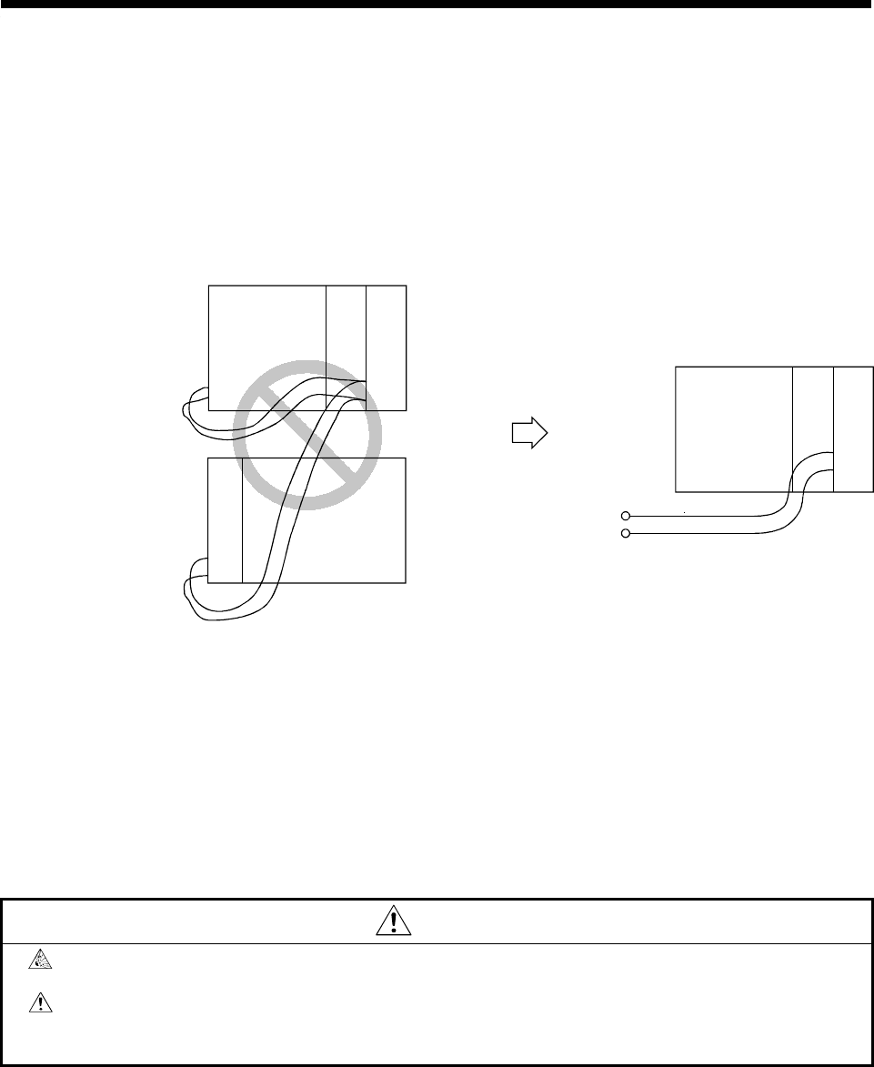
(1) Precautions when using the A1S62PN power supply module 24 VDC output
Do not connect 24 VDC outputs from multiple power supply modules in parallel
to supply a single I/O module. The power supply modules will be damaged if
the outputs are connected in parallel. If the 24 VDC output capacity of a single
power supply module is insufficient, supply power from an external 24 VDC
power supply.
2
4VDC
2
4VDC
Power supply module
I/O
module
CPU module
24VDC
External power supply
I/O
module
CPU module
(2) Twist 100 VAC, 200 VAC, and 24 VDC wires together as tightly as possible.
Connect units together over the minimum distance.
(3) To minimize the voltage drop, use the thickest 100 VAC, 200 VAC, and 24
VDC wires possible (2 mm
2
max.).
(4) Wiring the I/O equipment
(a) Wires between 0.75 mm
2
and 1.5 mm
2
can be connected to the terminal
block, but 0.75 mm
2
wires are recommended.
(b) If wires pass through a conduit, the conduit must be grounded.
CAUTION
Do not connect 24 VDC outputs from multiple power supply modules in parallel to supply a single
I/O module. This can damage or destroy the power supply modules.
Do not position the 100 VAC, 200 VAC or 24 VDC cables close to, or bundle them with, power-
circuit (high-voltage, high-current) cables or I/O signal cables. A clearance of at least 100 mm
(3.94 in) to other cables is required.


