1. SPECIFICATIONS OF MOTION SYSTEM COMPONENTS
1
−
28
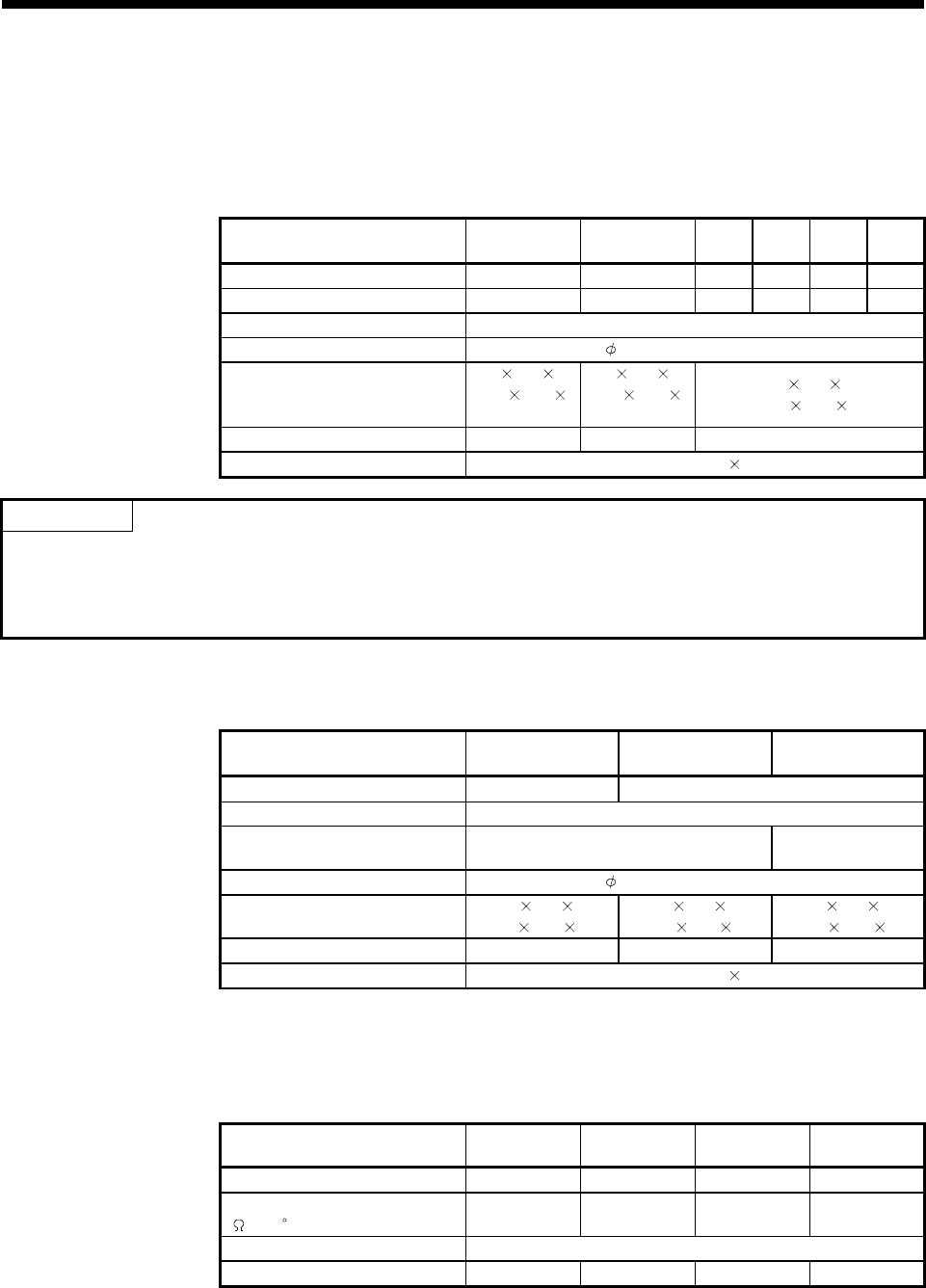
1.5.3 Base Units and Extension Cables
(1) Performance specifications
(a) Base unit specifications
1) Main base unit specifications
Table 1.6 Table of Main Base Unit Specifications
Model Name
Item
A172B A175B A178B
A178B
-S1
A178B
-S2
A178B
-S3
No. of motion slots 1 1 1248
No. of sequencer slots 1 4 7640
Extension connections OK
Mounting hole size 6 dia. slot (for M5 screw)
External dimensions mm(inch)
220
130 28
(8.67
5.12
1.1)
325
130 28
(12.8
5.12
1.1)
430
130 28
(10.93
5.12 1.1)
Weight kg (lb) 0.51 (1.12) 0.75 (1.66) 0.97 (2.14)
Accessories Mounting screws M5 25 4 pcs
POINT
Configure a system by choosing the motion modules and MELSEC-A series I/O modules so that the sum
of 5VDC consumed currents of the motion modules, MELSEC-A series I/O modules, synchronous
encoders and manual pulse generators connected to the main base unit is within 5 (A) for the
A172SHCPUN or 3 (A) for the A171SHCPUN.
2) Extension base unit specifications
Table 1.7 Table of Extension Base Unit Specifications
Model Name
Item
A1S65B A1S68B A168B
Max. I/O modules mountable 5 modules 8 modules
Power supply module Must be mounted
Connectivity of second/ subsequ-
ent stage of extension base unit
Second/subsequent
stage unconnectable
Only GOT
connectable
Mounting hole size 6 dia. slot (for M5 screw)
External dimensions mm(inch)
315
130 28
(12.4
5.12 1.1)
420
130 28
(16.55
5.12 1.1)
420
130 28
(16.55
5.12 1.1)
Weight kg (lb) 0.71 (1.56) 0.95 (2.09) 0.95 (2.09)
Accessories Mounting screws M5 25 4 pcs
(b) Specifications of extension cable
The specifications for extension cables which can be used with the motion
system are shown in Table 1.8.
Table 1.8 Table of Extension Cable Specifications
Model Name
Item
A1SC01B A1SC03B A1SC12B A1SC30B
Cable length m (inch) 0.055 (2.17) 0.33 (12.99) 1.2 (47.24) 3.0 (118.11)
Resistance of 5 VDC supply line
(
at 55
C
)
0.22 0.021 0.055 0.121
Application Connecting main base unit to extension base unit
Weight kg (lb) 0.025 (0.06) 0.10 (0.22) 0.20 (0.44) 0.4 (0.48)


