


4. TRIAL RUN AND ADJUSTMENT
4
−
3
4.2 Trial Run and Adjustment Procedure
POINTS
(1) Make note of motor model names before the motor is installed on a
machine. The motor name plate may not be visible after the motor is
installed.
(2) The machine may make unpredictable movements after a servo amplifier
or servomotor is first turned on. To prevent accidents, check the
operation of each individual motor.
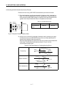
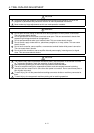
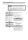
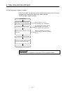
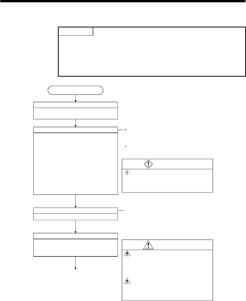
Servo start-up procedure
Trun CPU module Power Off
Make sure that the CPU module power
supply is off.
The mode indicated in the brackets ([ ]) at top left
of each step is the mode for checking or setting
by the peripheral device.
Check wiring and module installation
(1) Make sure that all modules are correctly
mounted in the correct position.
(2) Check that connectors are correctly
inserted.
(3) Make sure all terminal screws are tight.
(4) Check servo amplifier and other ground
wires.
(5) Check motor wiring (U, V, W).
(6) Check the regenerative resistor option
wiring.
(7) Check the emergency stop circuit.
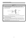
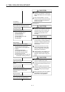
Check system settings
Set the operation axis number.
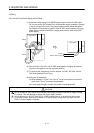
Turn on power
Ensure that the CPU module RUN/STOP key
is set to STOP.
Turn on the CPU module power.
· See Section 1.5.3(6) for information which
modules can be mounted in the main base
unit and the mounting positions.
· See Section 3.3 for information on mounting
modules.
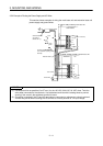
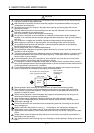
WARNING
Ground controllers, servo amplifiers, and
servomotors to 100W ground resistance,
or less (class 3 grounding). Do not share a
common ground with other equipment.
See Section 1.5.6(3).
(Note) An error may occur if the power is turned
on before system settings are made.
If this happens, make the system
settings, then reset the CPU.
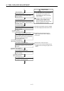
CAUTION
If a regenerative resistor is used, ensure
that an alarm signal cuts off the power
supply, otherwise damage to the regenera-
tive transistor, overheating of the regenera-
tive resistor, or even fire may result.
To prevent fires, take flameproofing measu-
res inside the control box where the servo
amplifier and regenerative resistor are
located and use non-flammable wiring.
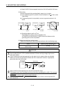
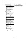
1)