


4. TRIAL RUN AND ADJUSTMENT
4
−
1
4. TRIAL RUN AND ADJUSTMENT
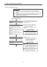
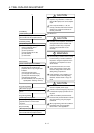
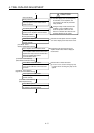
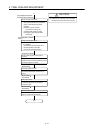
This chapter describes the checking items and procedures necessary for trial run
and adjustment for those who will perform trial run and adjustment of the motion
system.
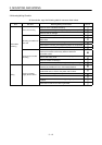
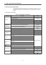
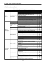
4.1 Checklist before Trial Operation
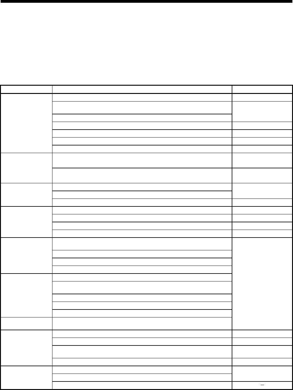
Table 4.1 Checklist before Trial Operation
Model Name Check Item Reference
(1) Is memory protection switch ON? 1.5.1 (5)
(2) Is the memory cassette battery (A6BAT) lead connector fully inserted into the
PCB pin connector.
(3) Is the battery voltage normal? (Nominal value: 3.6 V)
1.5.7
(4) Are the supply voltage and power supply module rated voltage correct? 1.5.2
(5) Are FG and LG wired correctly? 3.5.2
(6) Are terminal screws correctly tightened? 3.5.1 (6)
CPU module
(7) Are cable sizes correct? 3.5.1
(1) Is the module mounted in the correct position (option slot)? 1.5.4 (3) (a)
A172SENC manual
pulse generator/
synchronous encoder
interface module
(2) Is the interface with external equipment correct?
1.5.4 (3) (b)
1.5.4 (3) (c)
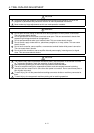
(1) Are the mounted module models correct?
(2) Is the mounting order correct?
1.5.3 (3)
Main base unit
(3) Are the modules correctly mounted? 3.3
(1) Is the correct power module model mounted? 1.5.2 (2)
(2) Are FG and LG wired correctly? 3.5.2
(3) Are terminal screws correctly tightened? 3.5.1 (6)
Extension base power
supply module
(4) Are cable sizes correct? 3.5.1
(1) Do cables connected to each terminal of the terminal block match the signal
names?
(2) Are terminal screws correctly tightened?
(3) Are cable sizes correct?
I/O module
(4) Is the external power supply correctly connected? (24 VDC, 5 VDC)
(1) Are the setting switches correctly set?
(2) Do cables connected to each terminal of the terminal block match the signal
names?
(3) Are terminal screws correctly tightened?
(4) Are cable sizes correct?
Special-function
module
(5) Is the external power supply correctly connected? (24 VDC, 5 VDC)
A1SG62 dummy
module
(1) Is the point-setting switch correctly set?
A1SCPU User's Manual
(1) Is the extension base unit model correct (A1S65B or A1S68B or A168B)? 1.5.3
(2) Are the mounted module models correct? 1.5.3 (3)
(3) Check that the total I/O module and special-function module I/O points does
not exceed the number of CPU module I/O points.
1.5.1
Extension base unit
(4) Are the modules correctly mounted? 3.3
(1) Is the extension cable connector correctly inserted in base unit connector?
(2) Is the extension cable connector position correct?
1.5.3
Extension cable
(3) Does the total length of the extension cables exceed 3 m (118.11 inch)?