


1. SPECIFICATIONS OF MOTION SYSTEM COMPONENTS
1
−
38
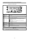
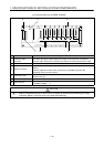
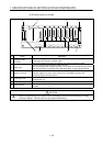
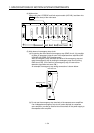
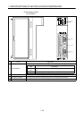
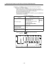
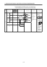
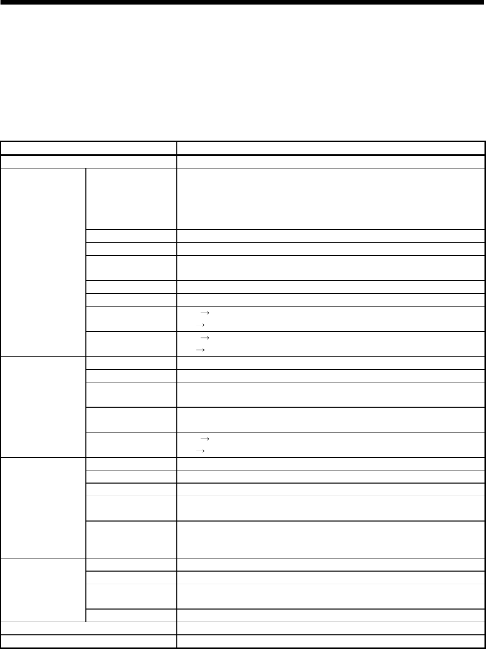
1.5.4 Manual Pulse Generator/Synchronous Encoder Interface Module
A172SENC receive external signals required for positioning control (motion control
signals and tracking inputs), manual pulse generator inputs, and synchronous
encoder inputs.
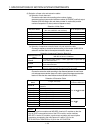
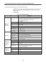
(1) Specifications
Table 1.9 A172SENC Specifications
Item Specification
Model Name A172SENC
No. of inputs
Motion control signals: 32 points
(8 points each for upper stroke limit, lower stroke limit, STOP input, near-
zero point DOG/speed-position changeover signal)
Tracking enable signal : 1 point
Total : 33 points
Rated input voltage 12/24VDC
Rated input current 12VDC 2mA/24VDC 4mA
Operating voltage
range
10.2 to 26.4VDC
ON voltage/current 7.0 VDC min./1.0 mA min.
OFF voltage/current 1.8 VDC max./0.18 mA max.
Response time
OFF
ON 2 ms max.
ON
OFF 3 ms max.
Motion control
signal input,
tracking input
Tracking input
response time
OFF
ON 0.5 ms max.
ON
OFF 0.5 ms max.
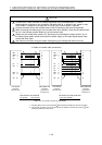
No. of outputs 1 point
Rated load voltage 24 VDC
Operating load
voltage range
21.6 to 30 VDC (peak voltage 30 VDC)
Maximum load
current
0.1 A (max. rush current: 0.4A, 10 ms max.)
Brake output
Response time
OFF
ON 2 ms max.
ON
OFF 2 ms max.
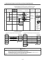
No. of modules 1
H voltage 3.0 to 5.25 V
L voltage 0 to 1.0 V
Maximum input
frequency
100 kpps max.
Manual pulse
generator input or
incremental
synchronous
encoder
Applicable type
Voltage-output type (5 VDC), Recommended product: MR-HDP01
Differential-output type: 26LS31 or equivalent
Selectable by connector wiring
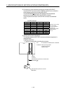
No. of modules 1
Applicable types MR-HENC
Position detection
method
Absolute
Serial absolute
synchronous
encoder input
Resolution 16384 PLS/rev
Power consumption (5 VDC) 0.42
Product weight (kg) (lb) 0.22 (0.49)