


1. SPECIFICATIONS OF MOTION SYSTEM COMPONENTS
1
−
56
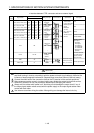
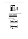
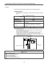
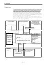
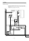
(3) Servo amplifier axis numbers and axis No. (dno.) setting
The axis No.s are used to set the axis numbers of the SSCNET-connected
servo amplifiers in the program. Axis No.s 1 to 32 can be set for the
A173UHCPU, 1 to 8 for the A172SHCPUN, and 1 to 4 for the A171SHCPUN.
To set the axis No.s, assign the axis No.s to the axis numbers set with the axis
selection switches (rotary switch) of the servo amplifiers (Positions 0 to 7 of the
rotary switch correspond to d1 to d8 on the system settings screen. (On the
A171SHCPUN, positions 0 to 3 of the rotary switch correspond to d1 to d4.)) to
each SSCNET line in the system settings of the positioning software package.
You cannot set the same axis number and axis No. (dno.) more than once.
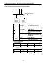
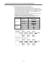
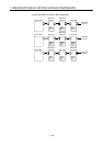
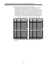
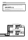
Correspondences between dno.s and servo amplifier rotary switches
dno.
*1
SSCNET
Line
Servo Amplifier's
Rotary Switch
dno.
*1
SSCNET
Line
Servo Amplifier's
Rotary Switch
11 “0” 12 “0”
21 “1” 22 “1”
31 “2” 32 “2”
41 “3” 42 “3”
51 “4” 52 “4”
61 “5” 62 “5”
71 “6” 72 “6”
81 “7” 82 “7”
dno.
*1
SSCNET
Line
Servo Amplifier's
Rotary Switch
dno.
*1
SSCNET
Line
Servo Amplifier's
Rotary Switch
13 “0” 14 “0”
23 “1” 24 “1”
33 “2” 34 “2”
43 “3” 44 “3”
53 “4” 54 “4”
63 “5” 64 “5”
73 “6” 74 “6”
83 “7” 84 “7”
*1: dno. is the servo amplifier axis numbers displayed in the system settings of the
positioning software package. Set the axis No. relative to the dno. in system
settings.