


1. SPECIFICATIONS OF MOTION SYSTEM COMPONENTS
1
−
17
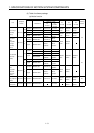
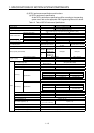
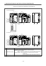
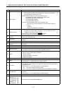
No. Name Applications
3) RUN indicator
!
Lit: Sequence program operating with RUN/STOP key switch set to RUN.
The indicator remains lit if an operation error occurs in the sequence
program (Refer to section 5.4.1 (10)).
!
Not lit: The RUN indicator is not lit in the following cases:
!
No 100/200 VAC power supplied to the CPU module.
!
RUN/STOP key switch is set to STOP.
!
A remote STOP is applied.
!
A remote PAUSE is applied.
!
Flashing: The RUN indicator flashes in the following cases:
!
Self-diagnosis function detected an error which stops sequence
program
operation.
!
A latch clear operation is conducted.
4) ERROR indicator
!
Lit: Self-diagnosis function detected an error.
However, the indicator does not light if it is set not to light for the error
detected in the order of priority settings.
!
Not lit: Normal, or error detected by
CHK
instruction.
!
Flashing: Sequence program annunciator (F) is on.
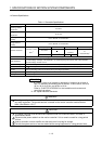
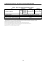
5)
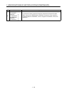
24 VDC, 24 GDC
terminals
!
Internally supplies output modules which require 24 VDC (supplied through external
wiring). (A171SHCPUN only)
6) FG terminal
!
A grounding terminal connected with the shielding pattern on the printed circuit
board.
7) LG terminal
!
Ground for power supply filter, with 1/2 the electrical potential of the input voltage.
8)
Power supply input
terminals
!
Connect the 100 VAC or 200 VAC power supply to the power supply input
terminals.
9) Terminal screws
!
M3.5 7
10) Terminal cover
!
A cover to protect the terminal block.
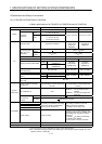
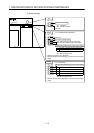
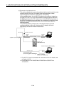
11) RS-422 connector
!
Connector to read, write, monitor, or test main programs with a peripheral device.
!
Covered by a cover when not connected to a peripheral device.
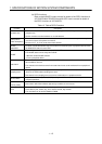
12) Covers
!
Open the protective cover for the printed circuit board, RS-422 connector, or
battery to carry out the following operations:
!
Set DIP switches.
!
Connect the battery connectors.
!
Replace the battery.
13) Module fixing screws
!
Screws to fix the module to the base unit.
14) Battery
!
Back-up battery for programs, devices in the latch range, and file registers.
(See Section 1.5.7 for the battery mounting procedure.)
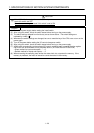
15) DIP switch 1
!
Installation switch
This switch is used to change the installed CPU module operating system with a
peripheral device.
(See Section 1.5.1 (5) for details about the switch settings.)
ON : Turn ON to install an operating system.
OFF : Turn OFF to enable CPU operation when OS installation is complete.
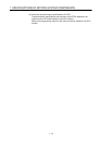
16) DIP switch 402
!
This switch selects the I/O control method and enables or disables memory
protection.
(See Section 1.5.1 (5) for details about the switch settings.)
17) Battery connector
!
A connector for connecting the battery unit
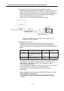
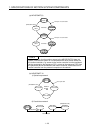
18)
Motion network connector
SSCNET1 to 2
(A172SHCPUN/
A171SHCPUN)
SSCNET1 to 4
(A173UHCPU)
!
Connectors to HR-H-BN/MR-J2S-B/MR-J2-B.