


5. INSPECTION AND MAINTENANCE
5
−
17
(9) Possible Problems with I/O Modules
This section describes possible problems with input and output circuits, and what to
do about them.
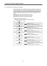
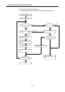
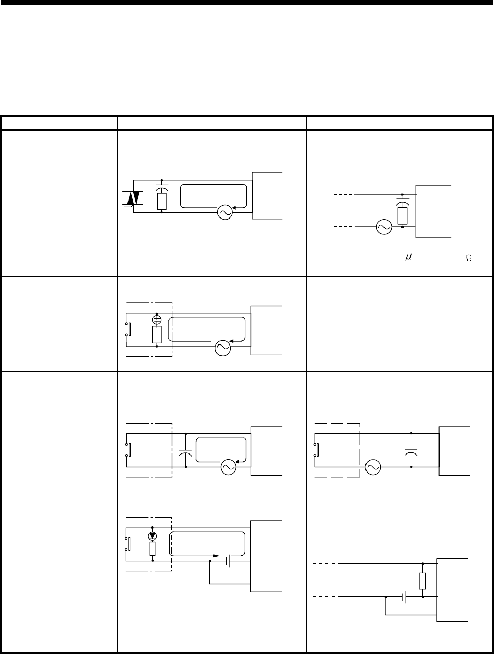
(a) Troubleshooting input circuits
Table 5.7 describes problems and corrective actions for input circuits.
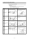
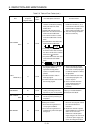
Table 5.7 Troubleshooting Input Circuits
Symptom Cause Corrective Action
Example 1
Input signal does not
turn OFF
•
Current leakage through input switch.
(Driven using a contactless switch, etc.)
Leak current
C
R
AC input
Input modul
e
Power supply
•
Connect an appropriate resistor to lower the
voltage between the input module terminals
below the OFF voltage.
C
R
AC input
Input module
Power supply
CR constant : 0.1 to 0.47
F + 47 to 120 (1/2
W) recommended
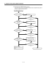
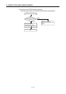
Example 2
Input signal does not
turn OFF
•
Driven using a limit switch with neon lamp.
Leak current
Power supply
Input module
AC input
•
See Problem 1, above.
•
Alternatively, provide a separate, independent
display circuit.
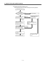
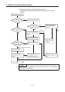
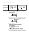
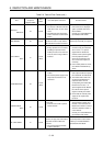
Example 3
Input signal does not
turn OFF
•
Leak current due to line capacity of wiring. Line
capacity (C) of twisted-wire pair is approx. 100
pF/m.
Power supply
Leak current
AC input
Input module
•
See Problem 1, above.
•
However, this problem does not arise when the
power supply is on the input equipment side.
Power supply
Input module
AC input
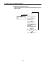
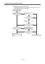
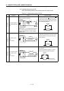
Example 4
Input signal does not
turn OFF
•
Driven using a limit switch with LED indicator.
Leak current
DC input (sink)
Input modul
e
•
Connect an appropriate resistor to lower the
voltage between the input module terminal and
common terminal below the OFF voltage, as
shown below.
Resistor
Input module
DC input (sink)
* The method of calculating the resistor to
connect is shown on the next page.