


2. DESIGN
2
−
13
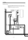
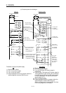
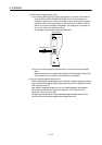
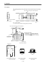
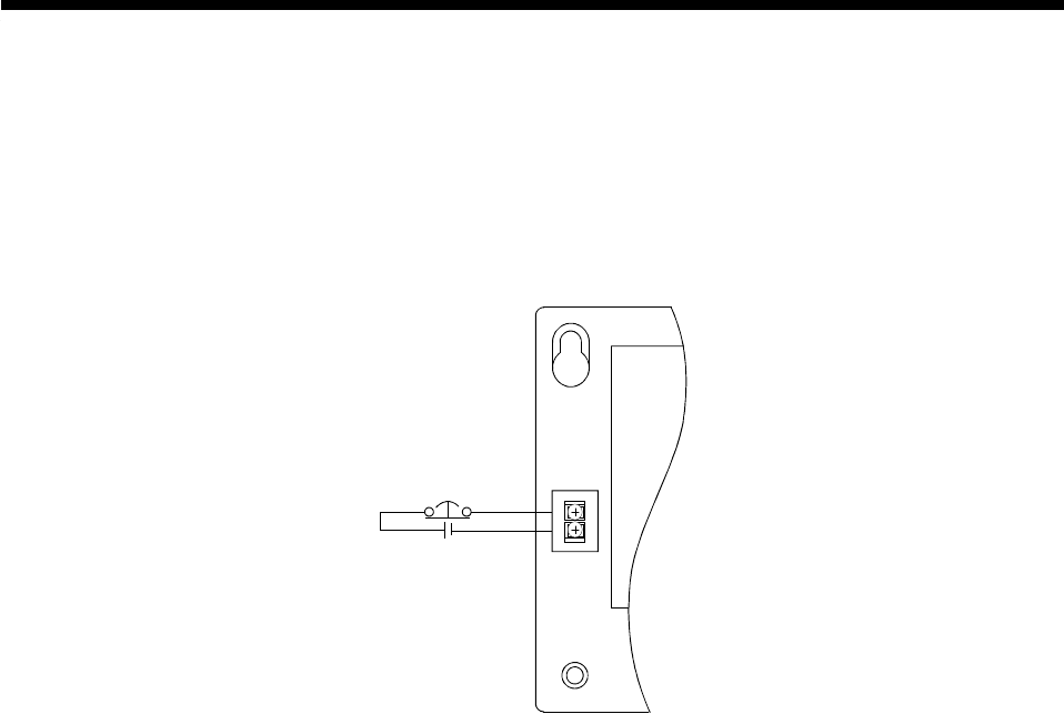
(2) Main base emergency stop circuit
(a) By opening the EMG circuit of the main base unit, all axes of the external
servo amplifiers (MR-H-BN/MR-J2S-B/MR-J2-B) can be brought to an
emergency stop at once. After an emergency stop, remove the emergency
stop factor and cancel the emergency stop (switch on the EMG circuit) to
switch on the servo amplifiers immediately. (An emergency stop does not
turn on the servo error detection signal.)
An emergency stop wiring example is shown below.
Emergency stop
24VDC
Main base unit
EMG
EMG.COM
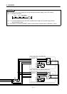
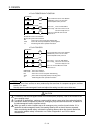
(b) Do not use the emergency stop terminals on the external servo amplifier
side.
When the external servo amplifier side requires its own emergency stop circuit,
use an external circuit to power off the external servo amplifiers.
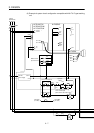
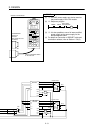
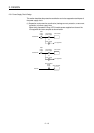
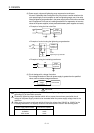
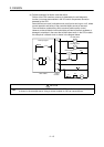
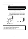
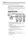
(3) External electromagnetic brake circuit
When configuring an electromagnetic circuit externally, create a sequence program
to turn off the electromagnetic brake output when the servo error detection or servo
OFF command turns off.
Also, write the sequence program to turn on the electromagnetic brake output
200ms after normal detection (servo error detection : OFF and servo OFF
command : ON) on the servo side.
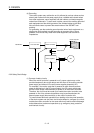
Configure the external circuit to open the electromagnetic brake terminal of the
servo motor when the electromagnetic brake output turns ON.