


1. SPECIFICATIONS OF MOTION SYSTEM COMPONENTS
1
−
39
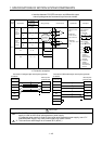
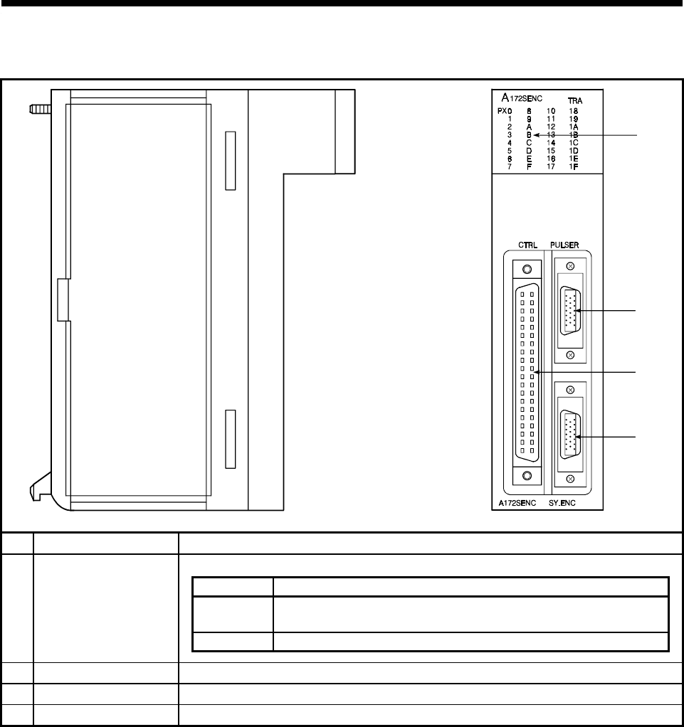
(2) Description of Parts
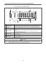
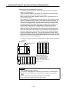
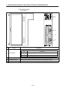
(a) A172SENC
1)
2)
3)
4)
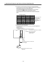
No. Name Application
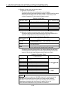
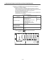
Display the input status from external equipment and errors detected by self-diagnosis.
LED Description
PX0 to
PX1F
Indicators to display the motion control signal input status of each
axis.
TRA Input start signal from synchronous encoder.
1) LED indicators
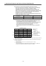
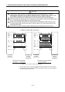
2) CTRL connector
Connector for motion control signal input and tracking signal input of each axis.
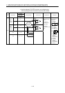
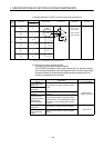
3) PULSER connector
Manual pulse generator/incremental synchronous encoder input connector.
4) SY.ENC connector
Serial absolute synchronous encoder input connector.