


1. SPECIFICATIONS OF MOTION SYSTEM COMPONENTS
1
−
35
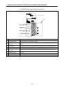
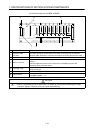
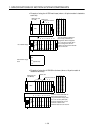
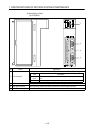
(6) Connection and I/O assignment of base units
This section explains the way to connect the base units and the concept of
sequence I/O assignment.
Use the extension cables for connection of the main base unit and extension
base unit and connection of the extension base units.
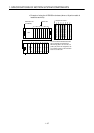
When connecting the graphic operation terminal (GOT) by the bus, load it to
the last extension base.
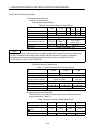
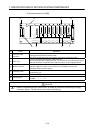
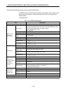
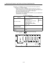
When automatic I/O assignment is executed (when the CPU module is started
without I/O assignment being made on the positioning software package), the
I/O numbers are automatically assigned, starting from 000, according to the
number of occupying points of the I/O modules loaded to the sequencer slots,
and each empty slot is assigned 16 points as occupied. Also, one base unit
occupies eight sequencer slots, independently of the physical number of
sequencer slots. Therefore, for example, when an extension base unit is
connected to the A175B main base unit (one motion slot and four sequencer
slots), the A175B main base unit has only four sequencer slots physically but
automatic assignment is made as if four 16-point slots are occupied between
the main and extension base units. To avoid the occupation of empty slots by
automatic assignment, setting the corresponding slots as empty (S0) in the I/O
assignment of the positioning software package allows the number of occupied
points to be set to 0 in the I/O assignment.
•
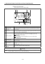
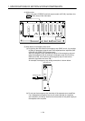
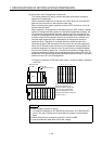
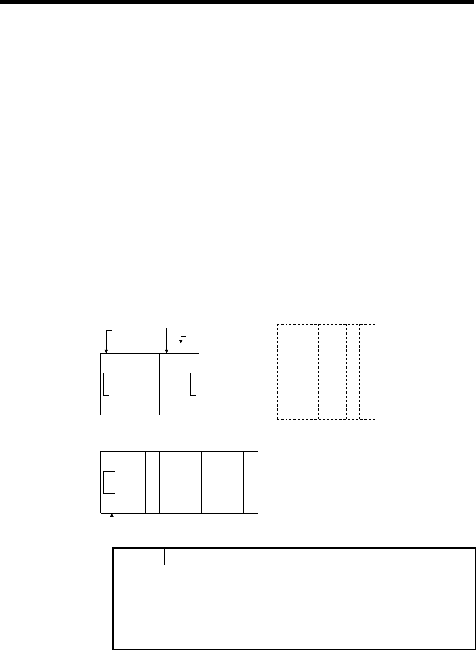
Example of using the A172B main base (when a 16-point module is loaded to
each slot)
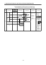
Sequencer slot No.
CPU
Power supply
module
A1S68B extension base unit
Motion slot
0
00
0F
to
10
80
8F
to
8
90
9F
to
9
A0
AF
to
11
B0
BF
to
12
C0
CF
to
13
D0
DF
to
14
E0
EF
to
15
F0
FF
to
Main base unit
(A172B)
Vacant, 16 points 10 to 1F
Vacant, 16 points 20 to 2F
Vacant, 16 points 30 to 3F
Vacant, 16 points 40 to 4F
Vacant, 16 points 50 to 5F
Vacant, 16 points 60 to 6F
Vacant, 16 points 70 to 7F
1
2
3
4
5
67
The I/O numbers indicated are
those set by automatic I/O
assignment. When empty slots
1 to 7 are set to 0 points (S0)
in the I/O assignment, the I/O
numbers of slot 8 of the extensio
n
base are 10 to 1F.
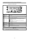
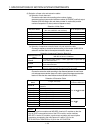
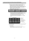
POINT
1) Max. number of actual I/O points
A173UHCPU:2048 points, A172SHCPUN:1024 points, A171SHCPUN:512
points. The real I/O points can be used within the range of one extension
base.
2) When using the bus connection type GOT, use the A168B.
3) Use the extension cable within 3m (9.84ft.) length.