


Digital Monitoring Products XR2500F Installation Guide
48
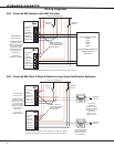
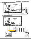
WIRInG dIaGRaMs
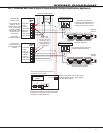
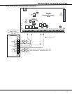
39.11 LX-Bus™ Module Connection
Model 716 Output
Expander Module
13m at 12 VDC
Model 717 Graphic
Annunciator
Module
10m at 12 VDC
To additional LX-Bus Modules
Red
Yellow
Green
Black
LX-Bus™ Wiring
Each LX-Bus Module must
have its own independent
address ranging from 00 to
99. A Supervisory zone must
be programmed into the
XR500 Series to properly
supervise each module.
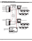
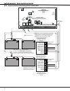
LX-Bus Expansion
Interface Card
DMP Models 481, 462N,
462P, 463G, or 472
S
S
S
S
S
S
S
S
S
S
S
S
S
= Supervised Circuit
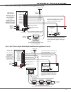
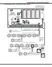
Open Collector
Annunciator Outputs
Relay 1
Relay 2
Relay 3
Relay 4
Optional LED wiring 50mA at
50 VDC resistive
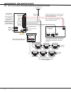
Form C Contacts
Typical
Normally Closed
Common
Normally Open
Optional LED wiring 50mA at
50 VDC resistive