


Digital Monitoring Products XR2500F Installation Guide
46
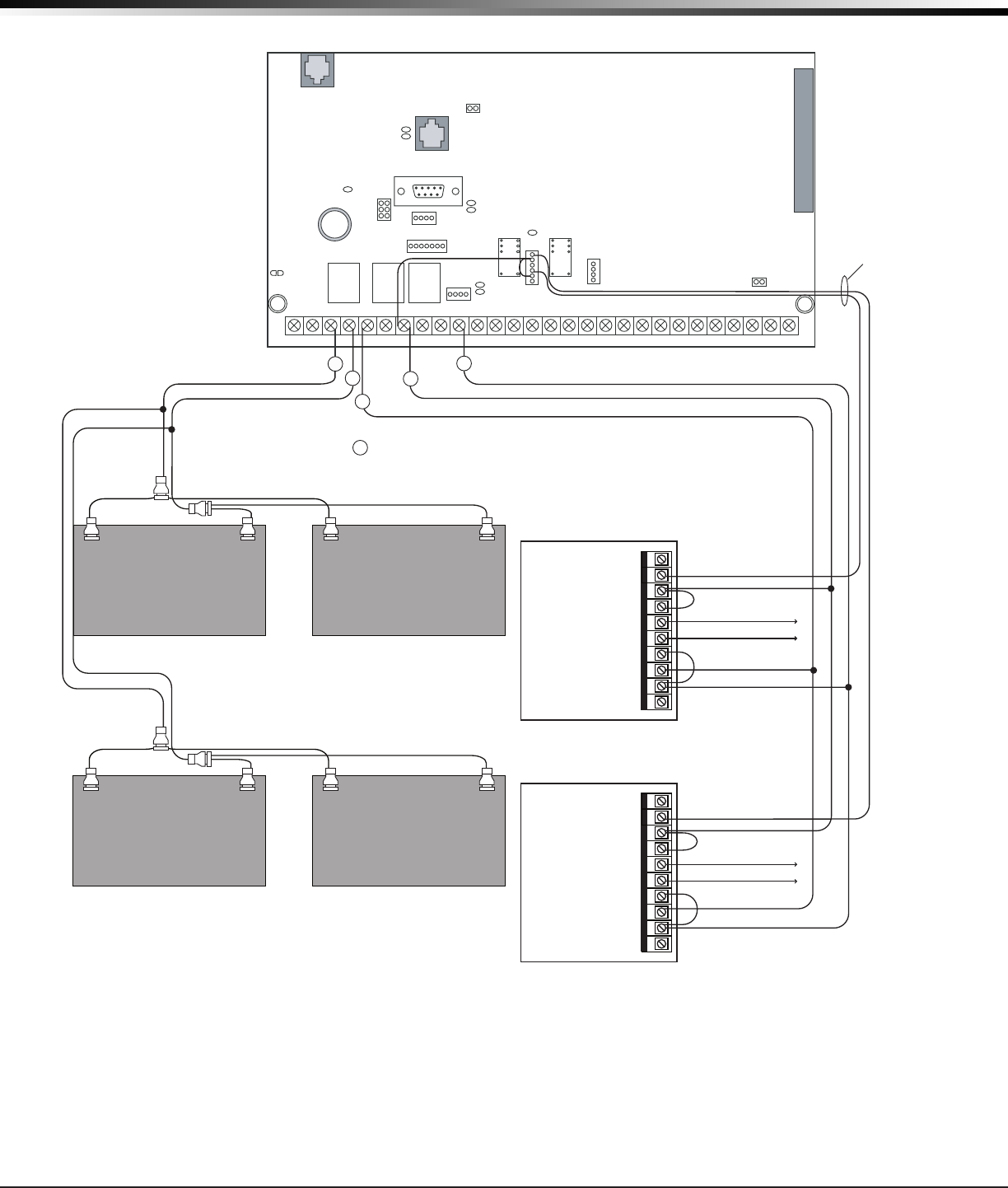
WIRInG dIaGRaMs
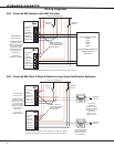
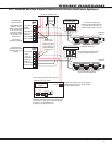
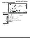
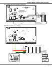
39.9 Remote Station Reversing Relay Connection
AC
12345678 10 11 12 13 14 15 16 17 18 199202122232425262728
+B BELLGND SMKGNDREDYEL GRNBLK Z1 Z2 Z3 Z4 Z5 Z6 Z7 Z8 Z9+Z9–Z10+Z10–AC –B GND GND GNDGND
K6 K7
J3
J10
J22
Battery
Start
J23
J21
RS-232
J4
Ta mper
J16
Reset
Outputs 3-6
J11
3
4
5
6
J2
J1
J6
Interface
Card
Expansion
Connector
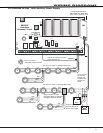
J2 Output Header
All outputs must be located within
the same room as the control panel.
Note: Output 1 must be programmed as a Fire Alarm
Output and Output 2 must be programmed as a Fire
Trouble Output. See Output Options section of the
XR500 Series Programming Guide (LT-0679).
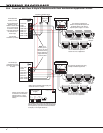
XR2500F
Command Processor™
Panel
Alternate Alarm
Combo Alarm
Auxiliary Power In
+ Signal Voltage In
+ To Remote Receiver
– To Remote Receiver
– Signal Voltage In
EARTH GROUND
GROUND
GROUND
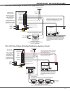
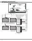
Up to 60 hours of battery standby time can be supplied
using multiple, sealed, Lead-Acid batteries.
See section titled Standby Battery Calculations.
To connect four batteries to the XR2500F Command
Processor™ Panel, use three Model 318 Battery Harnesses.
Reversing Relay Module
Radionics Model D127
5mA Standby, 55mA Alarm
@12 VDC
Alternate Alarm
Combo Alarm
Auxiliary Power In
+ Signal Voltage In
+ To Remote Receiver
– To Remote Receiver
– Signal Voltage In
EARTH GROUND
GROUND
GROUND
Reversing Relay Module
Radionics Model D127
5mA Standby, 55mA Alarm
@12 VDC
To Telephone Line
To Telephone Line
S = Supervised Circuit
Intended for connection to a
polarity reversal circuit of a
remote station receiving unit
having compatible ratings.
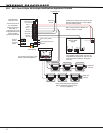
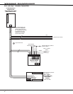
All modules must be installed in a
listed enclosure connected by no
more than 20 feet of conduit.
Fire Alarm Output 6 -
White/Orange
Fire Trouble Output 5 -
White/Yellow
S
S
S
S
Model 431
Output Harness
+ – +
–
Black
Red
+ – +
–
Black
Red
S
R
L
X
Out 1 Out 2
NO
C
NC
NO
C
NC
481 Zone Expansion Interface Card