


Digital Monitoring Products XR2500F Installation Guide
40
CoMPlIanCe
Wiring Diagrams
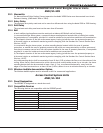
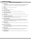
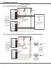
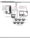
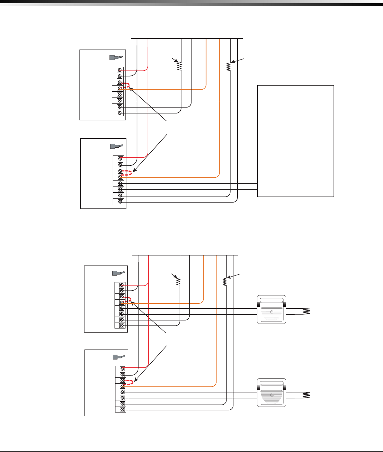
39.1 Prewired 866 Modules with NAC Extender
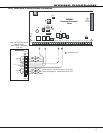
Model 310
1K EOL
Model 310
1K EOL
1 AUX PWR
2 GND
3 Alarm In
4 Bell PWR In
5 Bell Out +
6 Bell Out -
7 Bell Trouble
8 Bell Trouble
Normal/Silence Switch
1 AUX PWR
2 GND
3 Alarm In
4 Bell PWR In
5 Bell Out +
6 Bell Out -
7 Bell Trouble
8 Bell Trouble
Normal/Silence Switch
DMP Model 866
45mA @ 12 VDC
The 866 Notification
Appliance Circuit
Module in alarm draws
up to 31mA through
its Terminal 3 Alarm
Input and 45mA from
its Terminal 1 Aux
Power Input.
See the 866
Installation (LT-0059)
The Bell Output programming for Fire type zones must be set to Steady
Prewired to XR2500F panel
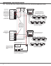
PowerPath NAC Extender
Models
PS-8
PS-8E
PS-6
PS-6E
See PowerPath installation for
detailed connection
instructions
Note: Terminals 3
and 4 jumper together
to supply Bell Power
from the panel
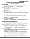
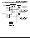
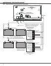
39.2 Prewired 866 Class B Style W Modules using Single Notication Appliance
Model 308
10K EOL
Model 308
10K EOL
Listed, Polarized
Notification Appliance
See the Notification
Appliance section for a
list of appliances.
The maximum
voltage drop
between the panel
Bell Output and the
Model 308 EOL is 1
VDC when a
separate power
supply is not used.
The Bell Output programming for Fire type zones must be set to Temporal.
Only one notification appliance may be used when not using a sync module.
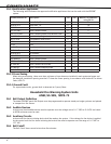
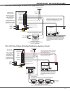
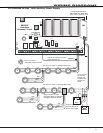
Model 310
1K EOL
Model 310
1K EOL
1 AUX PWR
2 GND
3 Alarm In
4 Bell PWR In
5 Bell Out +
6 Bell Out -
7 Bell Trouble
8 Bell Trouble
Normal/Silence Switch
1 AUX PWR
2 GND
3 Alarm In
4 Bell PWR In
5 Bell Out +
6 Bell Out -
7 Bell Trouble
8 Bell Trouble
Normal/Silence Switch
DMP Model 866
45mA @ 12 VDC
The 866 Notification
Appliance Circuit
Module in alarm draws
up to 31mA through
its Terminal 3 Alarm
Input and 45mA from
its Terminal 1 Aux
Power Input.
See the 866
Installation (LT-0059)
Prewired to XR2500F panel
Note: Terminals 3
and 4 jumper together
to supply Bell Power
from the panel