


XR2500F Installation Guide Digital Monitoring Products
27
InstallatIon
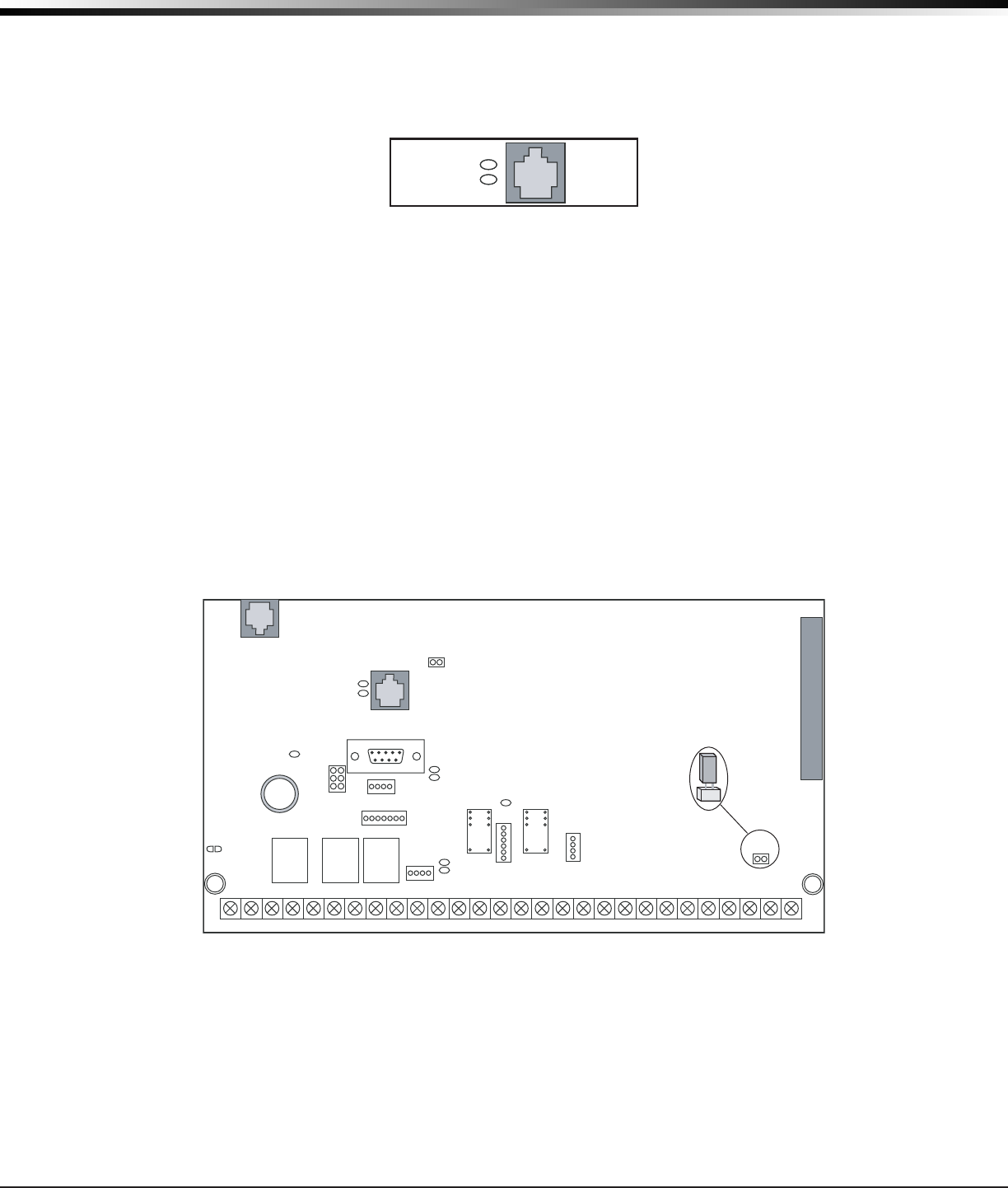
J1 Ethernet Connector
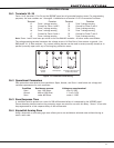
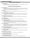
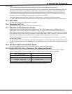
22.1 Description
TheJ1EthernetConnectorisavailabletoconnectdirectlytoanEthernetnetworkusingastandardpatch
cable.Themaximumlineimpedanceis100Ohms.
J1
Ethernet
Link LED
Activity LED
Figure 15: J1 Header and LEDs
22.2 Ethernet LEDs
ThetwoLEDs,locatedtotheleftofJ1EthernetConnector,indicatenetworkoperation.Thetop,Activity
LEDashesgreentoindicatethenetworktrafcisgood.Thebottom,LinkLEDashesyellowtoindicate
messagesarebeingsentandreceived.
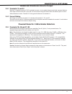
Reset and Tamper Headers
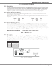
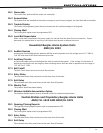
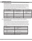
23.1 J16 Reset Header
Theresetheaderislocatedjustabovetheterminalstripontherightsideofthecircuitboardandisused
toresettheXR2500Fmicroprocessor.Toresetthepanelwhenrstinstallingthesystem,installthereset
jumperbeforeapplyingpowertothepanel.AfterconnectingtheACandbattery,removetheresetjumper.
Toresetthepanelwhilethesystemisoperational,forexample,priortoreprogramming,installthereset
jumperwithoutpoweringdownthesystem.Removetheresetjumperafteroneortwoseconds.
Afterresettingthepanel,beginprogrammingwithin30minutes.Ifyouwaitlongerthan30minutes,you
mustresetthepanelagain.
J6
Interface
Card
Expansion
Connector
Momentarily place the Reset
jumper over both of the J16
pins to reset the panel.
AC
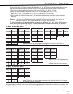
12345678 10 11 12 13 14 15 16 17 18 199202122232425262728
+B BELLGND SMK GNDREDYEL GRNBLK Z1 Z2 Z3 Z4 Z5 Z6 Z7 Z8 Z9+Z9–Z10+Z10–AC –B GND GND GNDGND
K6 K7
Output 1Output 2
J3
Phone Line
J10
J22
LX-Bus
Battery
Start
J23
J21
RS-232
Power
LED
J8
PROG
J4
Tamper
J16
Reset
Out1 Out2
Outputs 3-6
J11
3
4
5
6
J2
J1
Ethernet
R
L
X
OVC
Link LED
Activity LED
Figure 16: XR2500F Panel Showing the Reset Jumper
23.2 J4 Tamper Header
TheJ4headerisforusewiththeoptionalDMP306TamperHarness.Theharnessconnectstooneormore
tamperswitchesmountedinsidethepanelenclosuretosuperviseagainstunauthorizedenclosureopeningor
removal.Refertothewiringdiagramontheenclosuredoorforcorrecttamperswitchwiring.
How the Tamper Works
Iftheenclosureisopenedorremovedwhileoneormoreofthesystemareasarearmed,apaneltamper
alarmisindicated.Ifallareasaredisarmed,apaneltampertroubleisindicated.