


XR2500F Installation Guide Digital Monitoring Products
25
InstallatIon
J11 Annunciator Outputs
18.1 Description
Thefourprogrammableannunciatoroutputscanbeprogrammedtoindicatetheactivityofthepanelzones
orconditionsoccurringonthesystem.Annunciatoroutputs do not provide a voltage but instead switch-
to-groundavoltagefromanothersourceandareratedatamaximum30VDC@50mA.Theoutputscan
respondtoanyoftheconditionslistedintheDescriptionsectionofDryContactRelayOutputs.
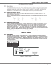
18.2 Model 300 Harness Wiring
AccesstheopencollectoroutputsbyinstallingDMP300Harnessonthe4-pinheaderlabeledJ11.The
output locations are shown below.
Note: For UL applications, devices connected to the outputs must be located within the same room as
the panel.
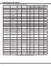
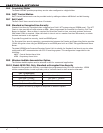
Output Color Wire Output Color Wire
3 Red 1 5 Green 3
4 Yellow 2 6 Black 4
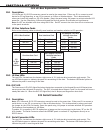
18.3 Model 860 Relay Module
ConnectaModel860RelayModuletotheJ11ontheXR2500Fpaneltoproviderelaysforoutputs3-6.Use
theserelaysforelectricalisolationbetweenthealarmpanelandothersystemsorforswitchingvoltage
tocontrolvariousfunctions.Powerissuppliedtotherelaycoilsfromasinglewireconnectedtothe
panelauxiliarypowerterminal7.Themoduleincludesonerelayandprovidesthreeadditionalsocketsfor
expansionofuptofourrelays.Mountthe860insidethepanelenclosureusingthe3-holepatternandplastic
standoffs.Refertothe860ModuleInstallSheet(LT-0484)asneeded.
Model 305 Relay Contact Rating: 1Ampat30VDC(allows.35powerfactor)
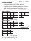
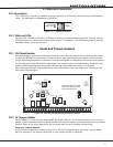
J23 6-Pin Header
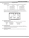
19.1 Description
TheXR2500FCommandProcessor™panelsupportsRS-232,LX-BusandWirelessBusexpansionoperation.
Theseoperationscannotfunctionatthesametime.InstallajumperononepairofJ23headerstoindicate
howthepanelisprogrammedtooperate.RefertothetablebelowwheninstallingajumperonJ23.When
ajumperisinstalledormovedonthe6-pinheader,brieyresetthepanelusingtheJ16jumpertoactivate
the selected operation.
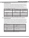
J23 6-Pin Header
Letter Operation
R StandardRS-232
L LX-Bus
X WirelessBus
LEDs
Xmit
Rec
J22
LX
J23
J21
RS-232
R
L
X
Overcurrent
(OVC) LED
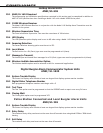
Figure 14: J23 6-Pin Header