


Digital Monitoring Products XR2500F Installation Guide
26
InstallatIon
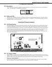
J22 LX-Bus Expansion Connector
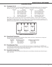
20.1 Description
J22LX-BusandJ21RS-232connectorscannotbeusedatthesametime.EitheruseJ21toconnectaserial
deviceforPCLogReporting,oruseJ22toconnectanLX-BusorWirelessdevice.Thisisdeterminedby
whereyouinstallthejumperonJ236-PinHeader.ResetthepanelusingJ16jumpertoactivateselectedJ23
operation.SeetheConnectingLX-BusandKeypadBusDevicessectionformaximumwiringdistances.
Note:DoNOTuseshieldedwirewhenusingtheLX-Bus.DoNOTconnectthewiresfromthe4-wireharness
to the panel terminals.
20.2 LX-Bus Interface Cards
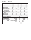
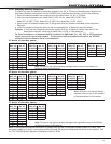
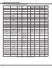
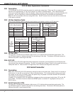
RefertothefollowingtablestoidentifyzonelocationsandnumbersrelativetoJ22operation.
J22 LX-Bus Enabled
AND
One Interface Card
OR
461 Adaptor Card and
Multiple Interface
Cards
LX-Bus Zone Numbers LX-Bus Zone Numbers LX-Bus Zone Numbers
1 500-599 2 600-699 2 (A) 600-699
3(B) 700-799
4 (C) 800-899
5 (D) 900-999
J22
LX-Bus
NOT
Enabled
One Interface Card
OR
461 Adaptor Card and
Multiple Interface
Cards
LX-Bus Zone Numbers LX-Bus Zone Numbers
1 500-599 1 (A) 500-599
2(B) 600-699
3(C) 700-799
4 (D) 800-899
5(E) 900-999
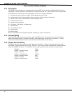
20.3 LX-Bus LEDs
ThetwoLEDs,locatednearthebottom-rightcornerofJ21indicatedatatransmissionandreceipt.The
topLEDashesgreentoindicatethepanelistransmittingLX-Busdata.ThebottomLEDashesyellowto
indicatethepanelisreceivingLX-Busdata.
20.4. OVC LED
TheOvercurrentLED(OVC)lightsRedwhenthedevicesconnectedtotheKeypadBusandLX-Bus(es)draw
morecurrentthanthepanelisratedfor.TheOVCislocatedaboveOutputs1and2onthepanelandturnsa
steadyRedwhenlit.WhentheOVCLEDlightsRed,theLX-Bus(es)andkeypadbusshutdown.
J21 Serial Connector
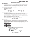
21.1 Description
Note:J22LX-BusandJ21RS-232connectorscannotbeusedatthesametime.EitheruseJ21toconnecta
serialdevice,oruseJ22toconnectanLX-BusorWirelessdevice.Thisisdeterminedbywhereyouinstall
thejumperontheJ236-PinHeader.ResetthepanelusingJ16jumpertoactivateselectedJ23operation.
Themaximumlineimpedanceis100Ohms.
ToenableJ21tooperateinRS-232modeplaceajumperonthetwopinsnexttotheletter“R”ontheJ23
6-Pinheader.TheSerialConnectorallowstheXR2500FpaneltotransmitPCLogReportsdirectlytoan
RS-232device.
21.2 Serial Connector LEDs
ThetwoLEDs,locatednearthebottom-rightcornerofJ21indicatedatatransmissionandreceipt.The
topLEDashesgreentoindicatethepanelistransmittingserialdata.ThebottomLEDashesyellowto
indicatethepanelisreceivingserialdata.