


Digital Monitoring Products XR2500F Installation Guide
42
WIRInG dIaGRaMs
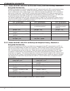
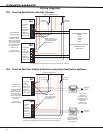
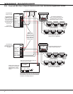
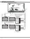
39.4 Prewired 866 Class B Style W Modules with Dual Notication Appliance Circuits
505-12 Power
Supply
J6
+ DC -
AC
Trouble
Batt
Trouble
J4
J3J2
Green
LED
AC
AC
+ BAT -
Red
LED
DC
12 VDC @ 5 Amps
Battery
Start
The Auxiliary Power Supply and Notification Circuit
Module trouble contact zone must be programmed
as a Supervisory Type zone and must be selected
for display in the keypad status list.
Auxiliary Power Supply must
be Listed for Fire Protective
Signaling Service. Power
Supplies must have battery
backup.
Listed, Polarized
Notification Appliances
Model 308
10K EOL
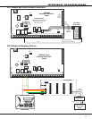
Sync module required when using
multiple notification appliances
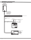
When using a separate power supply, the
maximum current is 3 Amps.
See the Notification Appliance
section for a list of appliances.
The maximum voltage drop
between the panel Bell Output and
the Model 308 is 1 VDC when a
separate power supply is not used.
The Bell Output
programming for Fire
type zones must be set
to Steady
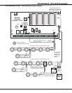
Model 310
1K EOL
1 AUX PWR
2 GND
3 Alarm In
4 Bell PWR In
5 Bell Out +
6 Bell Out -
7 Bell Trouble
8 Bell Trouble
Normal/Silence Switch
1 AUX PWR
2 GND
3 Alarm In
4 Bell PWR In
5 Bell Out +
6 Bell Out -
7 Bell Trouble
8 Bell Trouble
Normal/Silence Switch
DMP Model 866
45mA @ 12 VDC
The 866 Notification
Appliance Circuit
Module in alarm draws
up to 31mA through
its Terminal 3 Alarm
Input and 45mA from
its Terminal 1 Aux
Power Input.
See the 866
Installation (LT-0059)
Prewired to XR2500F panel
Note: If an
auxiliary power
supply is not used,
Terminals 3 and 4
jumper together to
supply Bell Power
from the panel
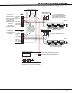
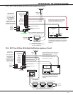
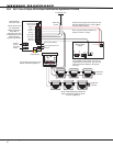
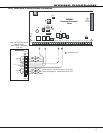
MINUS 2MINUS 1+OUT 1 +IN 1 +IN 2-AUD+AUD +OUT 2
DSM-12/24 Module
Listed, Polarized
Notification Appliances
Model 308
10K EOL
See the Notification Appliance
section for a list of appliances.
MINUS 2MINUS 1+OUT 1 +IN 1 +IN 2-AUD+AUD +OUT 2
DSM-12/24 Module